
𝐏&𝐎 𝐌𝐏𝐏𝐓 𝐟𝐨𝐫 𝐖𝐢𝐧𝐝 𝐄𝐧𝐞𝐫𝐠𝐲 𝐂𝐨𝐧𝐯𝐞𝐫𝐬𝐢𝐨𝐧 𝐒𝐲𝐬𝐭𝐞𝐦 𝐰𝐢𝐭𝐡 𝐆𝐫𝐢𝐝 𝐢𝐧 𝐌𝐀𝐓𝐋𝐀𝐁
- lms editor
- 2 days ago
- 4 min read

𝐏&𝐎 𝐌𝐏𝐏𝐓 𝐟𝐨𝐫 𝐖𝐢𝐧𝐝 𝐄𝐧𝐞𝐫𝐠𝐲 𝐂𝐨𝐧𝐯𝐞𝐫𝐬𝐢𝐨𝐧 𝐒𝐲𝐬𝐭𝐞𝐦 𝐰𝐢𝐭𝐡 𝐆𝐫𝐢𝐝 𝐢𝐧 𝐌𝐀𝐓𝐋𝐀𝐁
𝐏&𝐎 𝐌𝐏𝐏𝐓 𝐟𝐨𝐫 𝐖𝐢𝐧𝐝 𝐄𝐧𝐞𝐫𝐠𝐲 𝐂𝐨𝐧𝐯𝐞𝐫𝐬𝐢𝐨𝐧 𝐒𝐲𝐬𝐭𝐞𝐦 𝐰𝐢𝐭𝐡 𝐆𝐫𝐢𝐝 is a MATLAB/Simulink-based renewable energy model designed to extract maximum power from a wind turbine and inject the generated power into the grid.
This model is suitable for students, researchers, and engineers who want to understand wind energy conversion, PMSG operation, P&O MPPT control, DC-link regulation, grid inverter control, and power quality analysis in MATLAB.
𝐒𝐲𝐬𝐭𝐞𝐦 𝐎𝐯𝐞𝐫𝐯𝐢𝐞𝐰
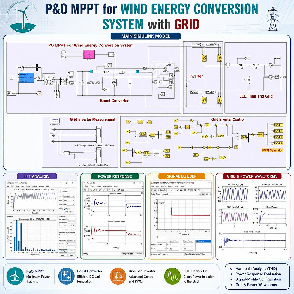
The system consists of a wind turbine, PMSG generator, diode rectifier, boost converter, DC link, single-phase inverter, LCL filter, and grid.
𝐒𝐞𝐜𝐭𝐢𝐨𝐧 | 𝐃𝐞𝐭𝐚𝐢𝐥𝐬 |
Software Platform | MATLAB/Simulink |
Renewable Source | Wind Energy |
Generator | PMSG |
Rectifier | Diode Rectifier |
Converter | Boost Converter |
MPPT Method | P&O MPPT |
DC Link | 400 V |
Inverter | Single-Phase Grid-Tied Inverter |
Filter | LCL Filter |
Grid Connection | Grid-Integrated Operation |
𝐖𝐨𝐫𝐤𝐢𝐧𝐠 𝐏𝐫𝐨𝐜𝐞𝐬𝐬
The wind turbine receives wind speed, generator speed, and pitch angle as input signals.
The wind turbine is connected to a PMSG generator.
The PMSG converts mechanical wind energy into electrical energy.
The AC output of the PMSG is converted into DC using a diode rectifier.
The rectified DC output is given to the boost converter.
The boost converter is controlled using the P&O MPPT method.
The P&O MPPT controller extracts maximum available power from the wind energy system.
The boosted DC output is connected to the DC link.
The DC-link voltage is maintained around 400 V.
The grid-tied inverter converts DC power into AC power.
The inverter output is connected to the grid through an LCL filter.
The generated wind power is injected into the grid with sinusoidal current waveform.
𝐂𝐨𝐧𝐭𝐫𝐨𝐥 𝐒𝐭𝐫𝐚𝐭𝐞𝐠𝐲
The system uses two major control sections.
𝐏&𝐎 𝐌𝐏𝐏𝐓 𝐂𝐨𝐧𝐭𝐫𝐨𝐥
The P&O MPPT controller measures the following signals:
Rectifier voltage
Rectifier current
Based on these inputs, the controller generates a duty cycle. This duty cycle is processed through a PWM generator to control the MOSFET switch of the boost converter.
The main purpose of P&O MPPT control is:
Maximum power extraction from the wind turbine
Efficient power transfer to the DC link
Stable operation under changing wind speed
Better utilization of available wind energy
𝐆𝐫𝐢𝐝 𝐈𝐧𝐯𝐞𝐫𝐭𝐞𝐫 𝐂𝐨𝐧𝐭𝐫𝐨𝐥
The inverter is controlled using a feedforward decoupling control concept.
The inverter control process includes:
Grid voltage measurement
PLL-based phase angle generation
Inverter current conversion into d-q form
Grid voltage conversion into d-q form
DC-link voltage control
d-axis current control
q-axis current control
PWM pulse generation for inverter switches
The q-axis reference is maintained at zero. Therefore, the system mainly transfers real power to the grid, while the reactive power is maintained close to zero.
𝐒𝐢𝐦𝐮𝐥𝐚𝐭𝐢𝐨𝐧 𝐏𝐚𝐫𝐚𝐦𝐞𝐭𝐞𝐫𝐬
𝐏𝐚𝐫𝐚𝐦𝐞𝐭𝐞𝐫 | 𝐕𝐚𝐥𝐮𝐞 / 𝐃𝐞𝐭𝐚𝐢𝐥 |
Software | MATLAB/Simulink |
Wind Turbine Rating | 3 kW |
Generator Type | PMSG |
MPPT Method | P&O MPPT |
Converter | Boost Converter |
Inverter | Single-Phase Grid-Tied Inverter |
Filter | LCL Filter |
DC-Link Voltage | 400 V |
Initial Wind Speed | 12 m/s |
Changed Wind Speed | 10.8 m/s |
Wind Speed Change Time | After 1 second |
Pitch Angle | 0 |
Grid Frequency | 50 Hz |
Reactive Power Reference | Zero |
THD Analysis Start Time | 0.3 seconds |
𝐒𝐢𝐦𝐮𝐥𝐚𝐭𝐢𝐨𝐧 𝐑𝐞𝐬𝐮𝐥𝐭𝐬
The simulation results show that the grid-integrated wind energy conversion system works effectively under wind speed variation.
𝐎𝐮𝐭𝐩𝐮𝐭 | 𝐎𝐛𝐬𝐞𝐫𝐯𝐚𝐭𝐢𝐨𝐧 |
Rectifier Power | Around 3 kW before wind speed reduction |
Boost Converter Power | Follows rectifier power response |
DC-Link Voltage | Maintained around 400 V |
Inverter Current | Reduces after wind speed reduction |
Grid Current | In phase with grid voltage |
Real Power | Injected into the grid |
Reactive Power | Maintained close to zero |
THD | Around 1.x% |
Power Quality | THD less than 5% |
𝐏𝐨𝐰𝐞𝐫 𝐐𝐮𝐚𝐥𝐢𝐭𝐲 𝐀𝐧𝐚𝐥𝐲𝐬𝐢𝐬
The THD is checked using the Powergui FFT Analysis Tool in MATLAB/Simulink.
𝐈𝐭𝐞𝐦 | 𝐃𝐞𝐭𝐚𝐢𝐥 |
Analysis Tool | Powergui FFT Analysis |
Signal Checked | Inverter current or grid current |
Fundamental Frequency | 50 Hz |
THD Value | Around 1.x% |
THD Limit | Less than 5% |
Result | Acceptable power quality |
The inverter current and grid current are sinusoidal. The grid voltage and current are in phase, which confirms real power injection into the grid.
𝐊𝐞𝐲 𝐅𝐞𝐚𝐭𝐮𝐫𝐞𝐬
Complete grid-integrated wind energy system in MATLAB
PMSG-based wind energy conversion
Diode rectifier for AC to DC conversion
P&O MPPT-based boost converter control
Stable DC-link voltage regulation
Feedforward decoupling-based inverter control
PLL-based grid synchronization
Real power injection into the grid
Reactive power maintained close to zero
THD analysis using FFT tool
Suitable for learning grid-connected renewable energy control
𝐀𝐩𝐩𝐥𝐢𝐜𝐚𝐭𝐢𝐨𝐧𝐬
Grid-connected wind energy system analysis
Renewable energy control system learning
P&O MPPT implementation for wind energy
PMSG-based wind turbine simulation
Grid-tied inverter control study
DC-link voltage regulation analysis
Power quality and THD evaluation
MATLAB/Simulink training for renewable energy systems
𝐖𝐡𝐲 𝐓𝐡𝐢𝐬 𝐌𝐨𝐝𝐞𝐥 𝐈𝐬 𝐔𝐬𝐞𝐟𝐮𝐥
This simulation model helps learners understand the complete operation of a grid-connected wind energy conversion system.
The model clearly explains:
How wind speed variation affects power generation
How P&O MPPT extracts maximum wind power
How the boost converter transfers power to the DC link
How DC-link voltage is maintained around 400 V
How the grid inverter injects power into the grid
How PLL and d-q control support grid synchronization
How THD can be checked using FFT analysis
𝐂𝐨𝐧𝐜𝐥𝐮𝐬𝐢𝐨𝐧
𝐏&𝐎 𝐌𝐏𝐏𝐓 𝐟𝐨𝐫 𝐖𝐢𝐧𝐝 𝐄𝐧𝐞𝐫𝐠𝐲 𝐂𝐨𝐧𝐯𝐞𝐫𝐬𝐢𝐨𝐧 𝐒𝐲𝐬𝐭𝐞𝐦 𝐰𝐢𝐭𝐡 𝐆𝐫𝐢𝐝 in MATLAB provides a clear and practical simulation platform for studying grid-connected wind energy systems.
The system maintains the DC-link voltage around 400 V, injects real power into the grid, reduces current according to wind speed variation, and achieves low THD below 5%.
This model is highly useful for learning PMSG wind generation, P&O MPPT, boost converter control, grid-tied inverter control, and power quality analysis in MATLAB/Simulink.
vidIQ


Comments