


Neural network with Model Predictive control of PMSM

Neural network with Model Predictive control of PMSM
𝐈𝐧𝐭𝐫𝐨𝐝𝐮𝐜𝐭𝐢𝐨𝐧
𝐍𝐞𝐮𝐫𝐚𝐥 𝐍𝐞𝐭𝐰𝐨𝐫𝐤 𝐰𝐢𝐭𝐡 𝐌𝐨𝐝𝐞𝐥 𝐏𝐫𝐞𝐝𝐢𝐜𝐭𝐢𝐯𝐞 𝐂𝐨𝐧𝐭𝐫𝐨𝐥 𝐨𝐟 𝐏𝐌𝐒𝐌 𝐢𝐧 𝐌𝐀𝐓𝐋𝐀𝐁/𝐒𝐢𝐦𝐮𝐥𝐢𝐧𝐤 combines intelligent reference-current generation with fast predictive switching control to achieve accurate speed tracking of a Permanent Magnet Synchronous Motor.
The control structure uses a Neural Network (NN) to generate the q-axis current reference and a Model Predictive Controller (MPC) to select the optimum inverter switching state. This combination provides fast dynamic response, controlled stator current, and accurate reference-speed tracking.
Neural network with Model Predictive control of PMSM
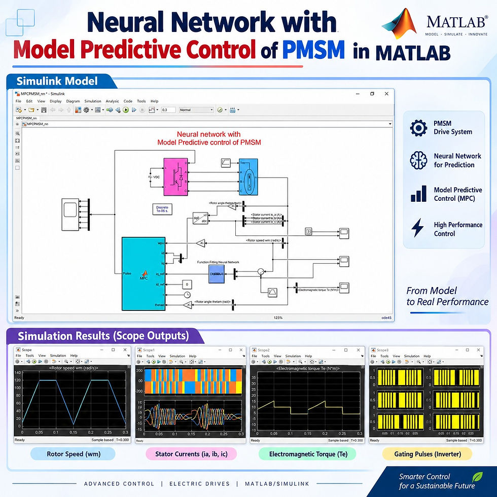
Permanent Magnet Synchronous Motors are widely used in high-performance electric drives because of their:
High efficiency
High power density
Fast dynamic response
High torque-to-weight ratio
Good speed-control capability
Compact construction
Conventional PI-based motor control can provide satisfactory performance, but its response depends strongly on controller tuning and operating conditions.
In this implementation, two intelligent control techniques are combined:
Neural Network – generates the required torque-producing current reference.
Model Predictive Control – predicts motor-current behavior for possible inverter switching states and selects the best switching action.
The complete control is implemented in MATLAB/Simulink.
𝐒𝐲𝐬𝐭𝐞𝐦 𝐎𝐯𝐞𝐫𝐯𝐢𝐞𝐰
The PMSM drive mainly consists of:
Component | Function |
DC Voltage Source | Supplies DC power to the drive |
Three-Phase Voltage Source Inverter | Converts DC power into controlled three-phase AC |
PMSM | Converts electrical power into mechanical output |
Rotor Position Measurement | Measures rotor angular position |
Speed Measurement | Provides actual motor speed |
Current Measurement | Measures stator phase currents |
Transformation Block | Converts phase currents into d-q quantities |
Neural Network | Generates q-axis reference current |
MPC Controller | Determines the optimum inverter switching state |
Gate Pulse Generator | Sends switching commands to the inverter |
The overall signal flow can be represented as:
Reference Speed → Neural Network → Current Reference → MPC → Inverter → PMSM → Feedback
𝐏𝐌𝐒𝐌 𝐌𝐞𝐚𝐬𝐮𝐫𝐞𝐦𝐞𝐧𝐭𝐬
Several motor variables are measured continuously for feedback control.
Main feedback signals
Rotor mechanical angle
Rotor electrical angle
Rotor speed
Phase-A stator current
Phase-B stator current
Phase-C stator current
d-axis current
q-axis current
Electromagnetic torque
The rotor mechanical angle is converted into the corresponding electrical rotor angle before being used by the control transformations.
The measured three-phase currents are converted into the rotating d-q reference frame so that the PMSM can be controlled using a field-oriented control principle.
𝐍𝐞𝐮𝐫𝐚𝐥 𝐍𝐞𝐭𝐰𝐨𝐫𝐤 𝐂𝐨𝐧𝐭𝐫𝐨𝐥
The neural network acts as the outer speed-control stage.
Neural network inputs
The network receives two important signals:
Speed error
Reference speed
The speed error represents the difference between the required motor speed and actual motor speed.
Neural network output
The neural network generates:
q-axis current reference, iq_ref
The q-axis current is mainly associated with the electromagnetic torque production of the PMSM.
For the implemented field-oriented control:
Control Variable | Setting |
d-axis current reference | 0 |
q-axis current reference | Generated by Neural Network |
Keeping the d-axis reference at zero provides a straightforward field-oriented control strategy for the PMSM.
𝐖𝐡𝐲 𝐔𝐬𝐞 𝐚 𝐍𝐞𝐮𝐫𝐚𝐥 𝐍𝐞𝐭𝐰𝐨𝐫𝐤?
The neural network learns the relationship between:
Reference speed
Actual speed behavior
Speed error
Required q-axis current command
Once properly trained, the network can generate the required current reference rapidly.
Main advantages
Reduces dependence on conventional fixed-gain tuning
Provides nonlinear mapping capability
Gives fast current-reference generation
Improves speed-command tracking
Can learn from previously collected input-output data
Integrates easily with MATLAB/Simulink
𝐍𝐞𝐮𝐫𝐚𝐥 𝐍𝐞𝐭𝐰𝐨𝐫𝐤 𝐓𝐫𝐚𝐢𝐧𝐢𝐧𝐠
Before inserting the neural network into the Simulink model, suitable input and output data are collected.
Training data structure
Data Type | Signal |
Input 1 | Speed error |
Input 2 | Reference speed |
Target Output | q-axis reference current |
The MATLAB fitting neural network environment can then be used to train the controller.
Typical training procedure
Prepare input data.
Prepare corresponding target-output data.
Open the neural network fitting application.
Select the input matrix.
Select the target-output matrix.
Configure the data orientation.
Train the neural network.
Evaluate regression performance.
Check mean squared error.
Retrain if necessary.
Export the trained network to Simulink.
𝐍𝐞𝐮𝐫𝐚𝐥 𝐍𝐞𝐭𝐰𝐨𝐫𝐤 𝐏𝐞𝐫𝐟𝐨𝐫𝐦𝐚𝐧𝐜𝐞
Two important parameters are considered while checking the trained network.
Performance Indicator | Desired Behavior |
Regression coefficient R | Close to 1 |
Mean Squared Error | Close to 0 |
Training error | Minimum |
Validation behavior | Stable |
Output tracking | Close to target data |
In the demonstrated training process, the regression value approaches 1, showing a strong relationship between the neural-network predictions and target values.
The mean squared error is also reduced to approximately the 10⁻³ range, indicating good learning performance for the collected dataset.
𝐌𝐨𝐝𝐞𝐥 𝐏𝐫𝐞𝐝𝐢𝐜𝐭𝐢𝐯𝐞 𝐂𝐨𝐧𝐭𝐫𝐨𝐥
After the q-axis reference current is generated, the inner current control is performed using Model Predictive Control.
Instead of using a conventional PWM current controller, the MPC evaluates the available switching combinations of the three-phase inverter.
For a two-level three-phase inverter, there are:
8 possible switching states
These extend from:
000
001
010
011
100
101
110
111
Each combination represents a particular inverter switching condition.
𝐖𝐨𝐫𝐤𝐢𝐧𝐠 𝐏𝐫𝐨𝐜𝐞𝐬𝐬
The complete controller operates in the following sequence:
The required PMSM speed is supplied as the reference speed.
Actual rotor speed is measured from the motor.
Reference and actual speeds are compared.
The resulting speed error is supplied to the neural network.
The reference speed is also supplied directly to the neural network.
The neural network produces the iq reference.
The id reference is maintained at zero.
Measured three-phase stator currents are transformed into actual id and iq currents.
The MPC evaluates all available inverter switching states.
The inverter voltage corresponding to each switching state is determined.
Future d-axis and q-axis currents are predicted.
A cost value is evaluated for every possible switching condition.
The controller identifies the state having the minimum cost.
The corresponding switching pattern is selected.
Six switching signals are applied to the three-phase inverter.
The PMSM responds to the selected inverter voltage.
Motor currents, rotor position, speed, and torque are measured again.
The process repeats continuously.
𝐌𝐏𝐂 𝐒𝐰𝐢𝐭𝐜𝐡𝐢𝐧𝐠 𝐒𝐭𝐚𝐭𝐞 𝐒𝐞𝐥𝐞𝐜𝐭𝐢𝐨𝐧
The important task of the MPC is to determine which inverter state gives the best predicted motor response.
Prediction procedure
For every candidate switching state, the MPC:
Determines the corresponding inverter voltage.
Converts the voltage into the appropriate reference frame.
Predicts future d-axis current.
Predicts future q-axis current.
Compares predicted currents with their reference values.
Calculates the corresponding cost.
Stores the cost value.
After checking all eight states, the MPC searches for the minimum-cost state.
That switching state is then applied to the inverter.
𝐂𝐨𝐬𝐭 𝐅𝐮𝐧𝐜𝐭𝐢𝐨𝐧 𝐑𝐨𝐥𝐞
The cost function is the decision-making element of the predictive controller.
Its purpose is simple:
Select the inverter switching condition that produces current behavior closest to the desired current references.
A lower cost represents a better predicted operating condition.
Therefore:
High cost → switching state is less suitable
Low cost → switching state is more suitable
Minimum cost → selected switching state
This mechanism allows the controller to decide the inverter switching condition directly during every control interval.
𝐂𝐨𝐧𝐭𝐫𝐨𝐥 𝐒𝐭𝐫𝐚𝐭𝐞𝐠𝐲
The complete strategy can be separated into two control levels.
Outer control: Neural Network
Responsible for:
Monitoring speed error
Processing speed reference
Generating iq reference
Supporting fast speed response
Inner control: Model Predictive Control
Responsible for:
Monitoring actual id and iq currents
Predicting future currents
Evaluating inverter switching states
Minimizing the current-tracking cost
Generating inverter gate pulses
This creates a hybrid intelligent-predictive controller:
NN Speed Control + FOC References + MPC Current Control
𝐑𝐞𝐟𝐞𝐫𝐞𝐧𝐜𝐞 𝐒𝐩𝐞𝐞𝐝 𝐏𝐫𝐨𝐟𝐢𝐥𝐞
A changing speed command is used to evaluate the dynamic behavior of the controller.
Time Interval | Reference Speed Behavior |
0 to 0.05 s | Increases from 0 to 120 rad/s |
0.05 to 0.10 s | Maintained at 120 rad/s |
0.10 to 0.15 s | Decreases from 120 rad/s to 0 |
0.15 to 0.20 s | Increases again |
0.20 to 0.25 s | Maintained near 120 rad/s |
0.25 to 0.30 s | Decreases again |
This type of changing command is useful for checking:
Acceleration performance
Steady-speed tracking
Deceleration response
Repeated transient behavior
Controller robustness during command changes
𝐌𝐚𝐢𝐧 𝐒𝐢𝐦𝐮𝐥𝐚𝐭𝐢𝐨𝐧 𝐏𝐚𝐫𝐚𝐦𝐞𝐭𝐞𝐫𝐬
Parameter | Value / Condition |
Motor type | PMSM |
Control method | Neural Network + MPC |
Inverter type | Three-phase two-level VSI |
Number of inverter switching states | 8 |
Maximum demonstrated speed reference | 120 rad/s |
d-axis current reference | 0 |
Neural network inputs | 2 |
Neural network output | iq reference |
Regression target | Close to 1 |
Reported MSE level | Approximately 10⁻³ |
Observed peak stator current during speed transition | Around 15 A |
Simulation duration shown | 0.30 s |
𝐒𝐢𝐦𝐮𝐥𝐚𝐭𝐢𝐨𝐧 𝐑𝐞𝐬𝐮𝐥𝐭𝐬
Different scopes are used to analyze the operation of the PMSM drive.
1. Rotor speed
The most important result is the comparison between:
Reference rotor speed
Actual rotor speed
The actual speed follows the changing reference command closely during acceleration, constant-speed operation, and deceleration.
This demonstrates successful coordination between the NN speed controller and MPC current controller.
2. Stator currents
The three-phase stator currents remain balanced while changing according to the motor operating condition.
During the demonstrated speed transition, the peak current is approximately:
15 A
This indicates controlled motor starting and smooth current behavior without an excessive current rise.
3. Inverter output
The three-phase voltage-source inverter generates switching voltage according to the state selected by the MPC.
The switching condition changes dynamically depending on:
Current references
Actual motor currents
Rotor position
Predicted current behavior
Minimum cost value
4. Electromagnetic torque
The electromagnetic torque changes according to the acceleration and speed requirements of the PMSM.
When the reference speed increases, additional electromagnetic torque is required.
During steady operation, torque settles according to the motor operating requirement.
During speed reduction, the torque response changes accordingly.
5. Inverter gating pulses
Six switching commands are generated for the three-phase inverter.
These pulses are not chosen randomly. They are determined from the minimum-cost switching state selected by the predictive controller.
The gate pattern therefore changes continuously according to the motor operating condition.
𝐑𝐞𝐬𝐮𝐥𝐭 𝐒𝐮𝐦𝐦𝐚𝐫𝐲
Observed Output | Performance |
Reference speed tracking | Accurate |
Acceleration | Smooth |
Deceleration | Properly controlled |
Peak stator current | Around 15 A |
Three-phase current behavior | Balanced |
Torque response | Follows operating demand |
Inverter switching | Determined by MPC |
Neural network output | Provides iq reference |
MPC objective | Minimum-cost switching selection |
Overall PMSM response | Fast and stable |
𝐊𝐞𝐲 𝐅𝐞𝐚𝐭𝐮𝐫𝐞𝐬
Neural-network-based speed controller
Model Predictive Current Control
Direct evaluation of eight inverter switching states
Field-oriented PMSM control
Zero d-axis current reference
Neural-network-generated q-axis current reference
Real-time motor-current prediction
Minimum-cost switching-state selection
Direct inverter gate-pulse generation
Rotor-position feedback
Speed feedback
Three-phase current feedback
Electromagnetic torque monitoring
Accurate reference-speed tracking
Smooth motor acceleration
Controlled stator-current response
MATLAB/Simulink implementation
𝐀𝐝𝐯𝐚𝐧𝐭𝐚𝐠𝐞𝐬 𝐨𝐟 𝐍𝐍-𝐌𝐏𝐂 𝐂𝐨𝐧𝐭𝐫𝐨𝐥
Neural Network advantages
Learns nonlinear relationships
Produces intelligent current references
Reduces dependence on fixed controller gains
Provides fast response to speed changes
Can be retrained with improved operating data
MPC advantages
Predicts future motor behavior
Handles inverter switching states directly
Provides fast current regulation
Uses an optimization-based decision process
Supports rapid transient response
Selects the best switching action during every sampling interval
Combined advantages
The hybrid approach offers:
Intelligent reference generation
Predictive current regulation
Fast speed tracking
Reduced current overshoot
Smooth transient performance
High-performance PMSM drive control
𝐖𝐡𝐲 𝐍𝐍 𝐚𝐧𝐝 𝐌𝐏𝐂 𝐖𝐨𝐫𝐤 𝐖𝐞𝐥𝐥 𝐓𝐨𝐠𝐞𝐭𝐡𝐞𝐫
The two controllers perform different but complementary functions.
Neural Network | Model Predictive Control |
Works mainly at the speed-control level | Works mainly at the current-control level |
Generates iq reference | Generates switching commands |
Learns from training data | Uses mathematical prediction |
Handles nonlinear input-output mapping | Evaluates possible future states |
Responds to speed error | Responds to current-tracking requirements |
The neural network decides how much torque-producing current is required, while MPC decides how the inverter should switch to obtain that current.
𝐀𝐩𝐩𝐥𝐢𝐜𝐚𝐭𝐢𝐨𝐧𝐬
Neural-network-assisted MPC for PMSM drives is suitable for studying advanced control in:
Electric vehicle traction drives
Industrial servo systems
Robotics
CNC machines
Electric propulsion systems
High-performance motor drives
Automated manufacturing equipment
Pump and compressor drives
Renewable-energy auxiliary drives
Aerospace actuator systems
Precision motion-control systems
𝐖𝐡𝐨 𝐂𝐚𝐧 𝐔𝐬𝐞 𝐓𝐡𝐢𝐬 𝐌𝐨𝐝𝐞𝐥?
This MATLAB/Simulink implementation is useful for:
Electrical engineering students
Power electronics learners
Motor-drive researchers
Control-system researchers
MATLAB/Simulink users
Electric vehicle researchers
AI-based control researchers
Engineers studying advanced PMSM control
It provides a clear understanding of how artificial intelligence, field-oriented control, predictive control, and inverter switching can be integrated into one PMSM drive.
𝐖𝐡𝐚𝐭 𝐂𝐚𝐧 𝐁𝐞 𝐀𝐧𝐚𝐥𝐲𝐳𝐞𝐝?
Using this model, users can investigate:
Speed tracking accuracy
Current response
Torque response
Switching behavior
Neural network regression
Neural network training error
MPC cost-function behavior
Switching-state selection
Acceleration performance
Deceleration performance
Motor transient response
Impact of different speed commands
Impact of different mechanical loads
𝐌𝐀𝐓𝐋𝐀𝐁/𝐒𝐢𝐦𝐮𝐥𝐢𝐧𝐤 𝐈𝐦𝐩𝐥𝐞𝐦𝐞𝐧𝐭𝐚𝐭𝐢𝐨𝐧 𝐅𝐥𝐨𝐰
A simple implementation sequence is:
Step 1: Configure the PMSM parameters.
Step 2: Connect the PMSM to a three-phase VSI.
Step 3: Measure rotor position, speed, current, and torque.
Step 4: Convert mechanical rotor position into electrical position.
Step 5: Transform measured phase currents into d-q currents.
Step 6: Generate the speed error.
Step 7: Supply speed reference and error to the neural network.
Step 8: Generate iq reference from the trained network.
Step 9: Keep id reference equal to zero.
Step 10: Supply reference and actual currents to the MPC.
Step 11: Evaluate all eight inverter switching states.
Step 12: Predict motor-current behavior.
Step 13: Identify the minimum-cost switching condition.
Step 14: Apply the corresponding inverter gate pulses.
Step 15: Analyze speed, current, torque, and switching waveforms.
𝐊𝐞𝐲 𝐋𝐞𝐚𝐫𝐧𝐢𝐧𝐠 𝐎𝐮𝐭𝐜𝐨𝐦𝐞𝐬
After studying this control structure, learners can understand:
PMSM field-oriented control
d-q current control
Neural network training
Speed-error processing
q-axis reference-current generation
Finite switching-state MPC
Current prediction
Cost-based optimization
VSI switching-state selection
PMSM speed tracking
MATLAB neural network integration with Simulink
𝐂𝐨𝐧𝐜𝐥𝐮𝐬𝐢𝐨𝐧
The Neural Network with Model Predictive Control of PMSM combines intelligent speed control with predictive inverter switching to obtain a fast and accurate motor-drive response.
The neural network receives the reference speed and speed error and generates the required q-axis current reference, while the d-axis reference is maintained at zero. The MPC then evaluates all eight inverter switching states, predicts motor-current behavior, determines the minimum-cost condition, and applies the corresponding gate pulses to the voltage-source inverter.
Simulation results demonstrate:
Accurate speed-reference tracking
Smooth acceleration and deceleration
Controlled stator-current response
Appropriate electromagnetic-torque variation
Dynamic inverter switching
Effective coordination between NN and MPC
This makes the model an excellent MATLAB/Simulink platform for learning and researching PMSM drives, neural network control, model predictive control, field-oriented control, and intelligent electric-drive systems.

Comments