


MATLAB Simulation of PV Battery Powered SRM Motor Based Electric Vehicle

MATLAB Simulation of PV Battery Powered SRM Motor Based Electric Vehicle
𝐈𝐧𝐭𝐫𝐨𝐝𝐮𝐜𝐭𝐢𝐨𝐧
The MATLAB Simulation of PV Battery Powered SRM Motor Based Electric Vehicle demonstrates the integration of solar photovoltaic generation, battery energy storage, power electronic converters, and a Switched Reluctance Motor (SRM) drive for electric vehicle operation.
PV Battery Powered SRM Motor Based Electric Vehicle
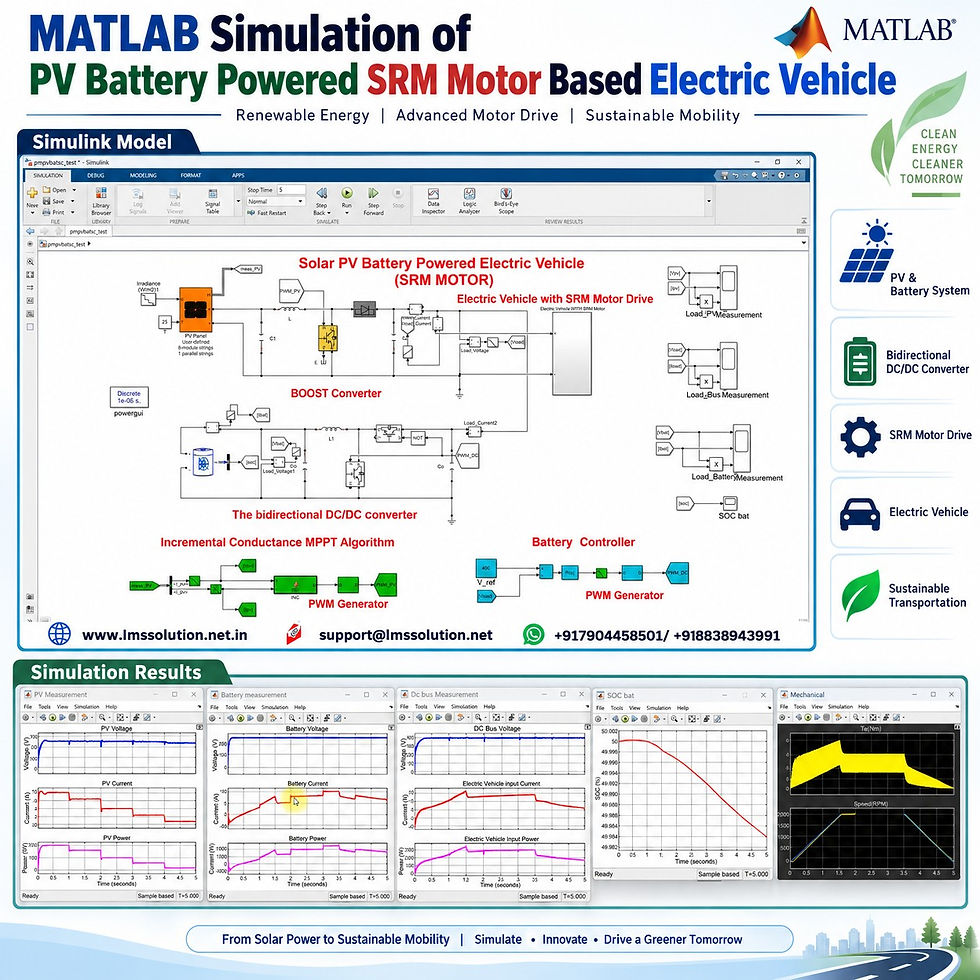
The complete system is developed in MATLAB/Simulink and demonstrates:
Solar PV power generation
Incremental Conductance Maximum Power Point Tracking (MPPT)
PV boost converter operation
Battery charging and discharging
Bidirectional DC/DC converter control
400 V DC-bus voltage regulation
SRM speed control
Acceleration, constant-speed, and deceleration operation
Dynamic solar irradiation conditions
Power sharing between PV, battery, and electric vehicle load
The model is useful for students, researchers, and engineers studying renewable-energy-based electric transportation, power converters, energy management, and electric motor drives.
𝐒𝐲𝐬𝐭𝐞𝐦 𝐎𝐯𝐞𝐫𝐯𝐢𝐞𝐰
The simulated electric vehicle system consists mainly of:
Solar PV array
DC/DC boost converter
Incremental Conductance MPPT controller
Common 400 V DC bus
Battery energy storage system
Bidirectional DC/DC converter
DC-bus voltage controller
Electric vehicle auxiliary load
SRM converter
Switched Reluctance Motor
Speed and current control system
The basic energy flow is:
Solar PV → Boost Converter → 400 V DC Bus → Electric Vehicle Load
and
Battery ↔ Bidirectional DC/DC Converter ↔ 400 V DC Bus
The battery therefore supports the vehicle whenever the available PV power is insufficient.
𝐌𝐚𝐢𝐧 𝐒𝐲𝐬𝐭𝐞𝐦 𝐏𝐚𝐫𝐚𝐦𝐞𝐭𝐞𝐫𝐬
Parameter | Value |
Number of PV panels | 8 |
Power of each PV panel | 250 W |
Total PV rated power | 2000 W |
PV connection | 8 panels in series |
Single-panel voltage at MPP | 30.7 V |
Single-panel current at MPP | 8.15 A |
Approximate PV array MPP voltage | 245 V |
Boost converter output | 400 V |
Common DC-bus voltage | 400 V |
Battery nominal voltage | 240 V |
Battery capacity | 48 Ah |
Initial battery SOC | 50% |
Motor type | Switched Reluctance Motor |
Maximum demonstrated motor speed | 2000 RPM |
Simulation duration | 5 s |
The PV array produces approximately 2 kW under standard operating conditions, while its voltage is increased from approximately 245 V to 400 V using the boost converter.
𝐒𝐨𝐥𝐚𝐫 𝐏𝐕 𝐒𝐲𝐬𝐭𝐞𝐦
The solar PV array acts as the primary renewable energy source.
Eight 250 W PV panels are connected in series to obtain:
Higher PV array voltage
Approximately 2 kW maximum rated PV power
Suitable input voltage for the boost converter
Since solar irradiation continuously changes, the output of a PV array also changes.
Therefore, simply connecting the PV array to the DC bus will not ensure maximum available power extraction.
For this reason, an Incremental Conductance MPPT algorithm is used.
𝐈𝐧𝐜𝐫𝐞𝐦𝐞𝐧𝐭𝐚𝐥 𝐂𝐨𝐧𝐝𝐮𝐜𝐭𝐚𝐧𝐜𝐞 𝐌𝐏𝐏𝐓
The Incremental Conductance MPPT controller receives two important measurements:
PV voltage
PV current
Using these signals, the controller continuously determines the correct operating point for extracting maximum available solar power.
Main MPPT tasks
The controller continuously:
Measures PV voltage and current.
Calculates the changes in PV operating conditions.
Identifies whether the PV array is operating:
Below the maximum power point
At the maximum power point
Above the maximum power point
Adjusts the converter duty cycle.
Keeps the duty cycle within predefined minimum and maximum limits.
Repeats the process throughout the simulation.
Important controller variables such as the previous voltage, current, power, and duty cycle are stored and updated during each execution step.
This allows the controller to track changes caused by varying solar irradiation.
𝐏𝐕 𝐁𝐨𝐨𝐬𝐭 𝐂𝐨𝐧𝐯𝐞𝐫𝐭𝐞𝐫
The PV voltage at the maximum power point is approximately 245 V, while the electric vehicle uses a 400 V common DC bus.
Therefore, a boost converter is placed between the PV array and the DC bus.
Its main functions are:
Increase PV voltage from approximately 245 V to 400 V
Receive the duty-cycle command from the MPPT controller
Allow maximum solar energy extraction
Transfer PV energy to the vehicle DC bus
The MPPT algorithm and boost converter therefore operate together as the PV energy conversion stage.
𝐁𝐚𝐭𝐭𝐞𝐫𝐲 𝐄𝐧𝐞𝐫𝐠𝐲 𝐒𝐭𝐨𝐫𝐚𝐠𝐞 𝐒𝐲𝐬𝐭𝐞𝐦
A 240 V, 48 Ah battery is incorporated into the system.
The initial battery State of Charge (SOC) is:
50%
Unlike the PV source, the battery must support bidirectional power flow.
It must be capable of:
Supplying energy to the electric vehicle
Receiving excess energy for charging
Supporting the DC bus during reduced PV generation
For this purpose, a bidirectional DC/DC converter is connected between the battery and the 400 V DC bus.
𝐁𝐚𝐭𝐭𝐞𝐫𝐲 𝐎𝐩𝐞𝐫𝐚𝐭𝐢𝐧𝐠 𝐌𝐨𝐝𝐞𝐬
Battery condition | Power direction | Purpose |
Charging | DC bus → Battery | Stores available excess power |
Discharging | Battery → DC bus | Supports the EV when PV power is insufficient |
Balanced operation | Small power exchange | Supports DC-bus regulation |
In the simulation sign convention:
Positive battery current/power represents discharging.
Negative battery current/power represents charging.
𝐁𝐢𝐝𝐢𝐫𝐞𝐜𝐭𝐢𝐨𝐧𝐚𝐥 𝐃𝐂/𝐃𝐂 𝐂𝐨𝐧𝐯𝐞𝐫𝐭𝐞𝐫
The battery voltage is approximately 240 V, whereas the common DC bus is maintained at 400 V.
The bidirectional converter therefore performs two important functions:
Voltage conversion
Bidirectional energy transfer
It allows the battery to dynamically respond to variations in:
PV generation
Vehicle power demand
Motor operating condition
DC-bus voltage
𝐁𝐚𝐭𝐭𝐞𝐫𝐲 𝐂𝐨𝐧𝐭𝐫𝐨𝐥 𝐒𝐭𝐫𝐚𝐭𝐞𝐠𝐲
The battery converter is controlled using a DC-bus voltage regulation strategy.
The control objective is to maintain:
DC Bus Voltage = 400 V
The controller performs the following sequence:
Measures actual DC-bus voltage
Compares it with the 400 V reference
Processes the voltage error through a PI controller
Generates the required duty-cycle command
Produces switching pulses through the PWM generator
Controls battery charging or discharging
Therefore, the battery acts as an important energy-balancing source.
𝐄𝐥𝐞𝐜𝐭𝐫𝐢𝐜 𝐕𝐞𝐡𝐢𝐜𝐥𝐞 𝐰𝐢𝐭𝐡 𝐒𝐑𝐌 𝐃𝐫𝐢𝐯𝐞
The electric vehicle section contains:
Auxiliary electrical load
SRM power converter
Switched Reluctance Motor
Rotor-position information
Motor current measurement
Electromagnetic torque measurement
Speed measurement
Speed controller
Current controller
The Switched Reluctance Motor converts electrical energy from the DC bus into mechanical energy for vehicle propulsion.
SRMs are attractive for electric drive applications because of their simple rotor construction and suitability for controlled variable-speed operation.
𝐒𝐑𝐌 𝐒𝐩𝐞𝐞𝐝 𝐂𝐨𝐧𝐭𝐫𝐨𝐥
The SRM drive uses a closed-loop speed-control structure.
The reference speed is compared with actual motor speed. The resulting error is processed through the speed controller to obtain the required motor-current reference.
The current controller then generates switching commands for the SRM converter.
This allows the motor to accurately follow the required driving-speed profile.
𝐕𝐞𝐡𝐢𝐜𝐥𝐞 𝐒𝐩𝐞𝐞𝐝 𝐏𝐫𝐨𝐟𝐢𝐥𝐞
The simulation demonstrates three main driving modes.
Time interval | Speed command | Vehicle operating mode |
0–1.5 s | 0 → 2000 RPM | Acceleration |
1.5–3.5 s | 2000 RPM | Constant-speed operation |
3.5–5 s | 2000 → 0 RPM | Deceleration |
This speed reference provides a simple representation of practical vehicle operation.
During acceleration
Motor speed increases.
Vehicle power demand increases.
Motor torque is relatively high.
Battery support may increase depending on available PV power.
During constant speed
Motor operates close to 2000 RPM.
Power demand becomes comparatively stable.
Actual motor speed follows the reference speed.
During deceleration
Reference speed decreases.
Motor speed gradually decreases.
Vehicle input current and power also reduce.
𝐃𝐲𝐧𝐚𝐦𝐢𝐜 𝐒𝐨𝐥𝐚𝐫 𝐈𝐫𝐫𝐚𝐝𝐢𝐚𝐭𝐢𝐨𝐧
To evaluate the response of the PV and battery system, solar irradiation is changed during the simulation.
The demonstrated profile reduces the irradiation in steps approximately every second.
Operating stage | Solar irradiation |
Stage 1 | 1000 W/m² |
Stage 2 | 800 W/m² |
Stage 3 | 500 W/m² |
Stage 4 | 300 W/m² |
Stage 5 | 100 W/m² |
This dynamic condition demonstrates how the MPPT controller and battery storage system work together when solar energy availability changes.
𝐖𝐨𝐫𝐤𝐢𝐧𝐠 𝐏𝐫𝐨𝐜𝐞𝐬𝐬
The complete operation can be understood in a few steps.
1. Solar energy generation
The PV array generates electrical energy according to the available irradiation.
2. Maximum power extraction
The Incremental Conductance MPPT controller determines the suitable boost-converter duty cycle.
3. Voltage boosting
The boost converter increases the PV voltage to the required DC-bus level.
4. DC-bus regulation
The common DC bus is maintained close to 400 V.
5. Battery power balancing
The battery charges or discharges depending on the difference between PV generation and vehicle demand.
6. SRM drive operation
The DC-bus power is supplied to the SRM converter and auxiliary vehicle loads.
7. Speed control
The motor controller makes the SRM follow the required acceleration, constant-speed, and deceleration commands.
𝐄𝐧𝐞𝐫𝐠𝐲 𝐌𝐚𝐧𝐚𝐠𝐞𝐦𝐞𝐧𝐭 𝐁𝐞𝐡𝐚𝐯𝐢𝐨𝐮𝐫
A major advantage of this configuration is its natural power-sharing capability.
When PV power is high
PV supplies most of the EV demand.
Excess energy can charge the battery.
Battery power requirement is reduced.
When PV power decreases
PV output current decreases.
PV output power decreases.
The battery changes toward discharge operation.
Battery energy compensates for the PV power deficit.
When vehicle power demand changes
The battery converter responds to maintain the required power balance while keeping the DC bus close to 400 V.
𝐂𝐨𝐧𝐭𝐫𝐨𝐥 𝐒𝐭𝐫𝐚𝐭𝐞𝐠𝐲
The complete model contains three major control loops.
Controller | Main input | Main output | Objective |
Incremental Conductance MPPT | PV voltage and current | Duty cycle | Extract maximum PV power |
Battery voltage controller | DC-bus voltage | PWM command | Maintain 400 V DC bus |
SRM speed controller | Reference and actual speed | Motor current reference | Track vehicle speed |
SRM current controller | Current reference and actual current | Converter pulses | Regulate motor current |
These controllers operate simultaneously to maintain stable and coordinated system performance.
𝐒𝐢𝐦𝐮𝐥𝐚𝐭𝐢𝐨𝐧 𝐑𝐞𝐬𝐮𝐥𝐭𝐬
Several important electrical and mechanical quantities are monitored in MATLAB/Simulink.
𝐏𝐕 𝐑𝐞𝐬𝐮𝐥𝐭𝐬
The PV measurement scope displays:
PV voltage
PV current
PV power
As irradiation decreases:
PV current decreases significantly.
PV power decreases accordingly.
PV voltage remains within the operating region controlled by MPPT.
The Incremental Conductance algorithm continuously tracks the changing operating point.
𝐃𝐂 𝐁𝐮𝐬 𝐑𝐞𝐬𝐮𝐥𝐭𝐬
The DC-bus scope displays:
DC-bus voltage
Electric vehicle input current
Electric vehicle input power
The important observation is that the:
DC-bus voltage remains approximately 400 V
even when:
Solar irradiation changes
PV power decreases
Motor speed changes
Vehicle power demand varies
This demonstrates the effectiveness of the battery converter control.
𝐁𝐚𝐭𝐭𝐞𝐫𝐲 𝐑𝐞𝐬𝐮𝐥𝐭𝐬
The battery scope shows:
Battery voltage
Battery current
Battery power
Battery SOC
Initially, the battery can operate in charging mode depending on the available solar power and vehicle demand.
As solar PV power decreases:
Battery current moves toward the positive direction.
Battery power becomes positive.
The battery enters discharging mode.
Additional battery energy is supplied to the vehicle.
This behaviour demonstrates effective power sharing between PV and battery sources.
𝐁𝐚𝐭𝐭𝐞𝐫𝐲 𝐒𝐎𝐂
The battery starts with approximately:
50% SOC
During discharge operation, SOC gradually decreases.
Because the simulation duration is only five seconds, the total change in SOC is small. However, the trend clearly indicates whether the battery is charging or discharging.
𝐒𝐑𝐌 𝐌𝐞𝐜𝐡𝐚𝐧𝐢𝐜𝐚𝐥 𝐑𝐞𝐬𝐮𝐥𝐭𝐬
The SRM results include:
Motor current
Motor flux
Electromagnetic torque
Actual rotor speed
Reference rotor speed
The actual SRM speed follows the commanded profile:
Accelerates to 2000 RPM
Maintains approximately 2000 RPM
Decelerates toward zero
This confirms the performance of the SRM closed-loop drive controller.
𝐊𝐞𝐲 𝐑𝐞𝐬𝐮𝐥𝐭 𝐒𝐮𝐦𝐦𝐚𝐫𝐲
Result | Observed behaviour |
PV power | Changes according to irradiation |
MPPT | Tracks the changing PV maximum-power operating point |
PV boost converter | Interfaces PV array with the 400 V bus |
DC-bus voltage | Maintained close to 400 V |
Battery | Changes between charging and discharging |
Battery SOC | Changes according to battery power direction |
EV input power | Changes according to driving demand |
Motor speed | Tracks the reference-speed command |
Motor torque | Changes according to acceleration and load demand |
Overall power flow | Balanced using PV and battery sources |
𝐊𝐞𝐲 𝐅𝐞𝐚𝐭𝐮𝐫𝐞𝐬
2 kW solar PV generation system
Eight series-connected PV panels
Incremental Conductance MPPT
PV DC/DC boost converter
400 V regulated DC bus
240 V, 48 Ah battery
Bidirectional battery converter
Battery charging and discharging operation
Dynamic solar irradiation
SRM-based electric vehicle drive
Closed-loop motor speed control
Acceleration and deceleration testing
PV, battery, DC-bus, and motor measurements
Complete MATLAB/Simulink implementation
Renewable-energy-based vehicle power management
𝐖𝐡𝐲 𝐔𝐬𝐞 𝐚𝐧 𝐒𝐑𝐌 𝐟𝐨𝐫 𝐚𝐧 𝐄𝐥𝐞𝐜𝐭𝐫𝐢𝐜 𝐕𝐞𝐡𝐢𝐜𝐥𝐞?
A Switched Reluctance Motor is an interesting option for electric transportation because it offers:
Simple rotor construction
No rotor windings
Robust mechanical structure
Wide-speed operating capability
Suitability for power-electronic control
Good performance under variable-speed operation
The SRM requires proper converter switching, current regulation, and rotor-position information, which are included in this simulation.
𝐖𝐡𝐲 𝐈𝐧𝐜𝐥𝐮𝐝𝐞 𝐁𝐚𝐭𝐭𝐞𝐫𝐲 𝐒𝐭𝐨𝐫𝐚𝐠𝐞?
Solar PV generation alone cannot continuously satisfy electric vehicle demand because sunlight is variable.
Battery storage helps by:
Supporting the EV during low irradiation
Absorbing excess PV energy
Stabilizing the common DC bus
Reducing the effect of rapid PV power changes
Providing power during acceleration
Improving overall energy availability
The combination of PV + Battery + SRM therefore provides a useful platform for studying renewable-powered electric mobility.
𝐀𝐩𝐩𝐥𝐢𝐜𝐚𝐭𝐢𝐨𝐧𝐬
This MATLAB/Simulink model is useful for studying:
Solar-powered electric vehicles
Hybrid PV-battery energy systems
Electric vehicle motor drives
SRM speed-control techniques
Battery energy management
Maximum Power Point Tracking
Bidirectional converter control
DC-bus voltage regulation
Renewable energy integration
Electric transportation systems
Power electronic converter control
Dynamic energy-flow analysis
𝐖𝐡𝐚𝐭 𝐂𝐚𝐧 𝐁𝐞 𝐋𝐞𝐚𝐫𝐧𝐞𝐝 𝐅𝐫𝐨𝐦 𝐓𝐡𝐢𝐬 𝐒𝐢𝐦𝐮𝐥𝐚𝐭𝐢𝐨𝐧?
By studying this model, learners can understand:
How a PV array is connected to an EV DC bus
Why MPPT is required for solar PV
How Incremental Conductance MPPT works
How a boost converter interfaces the PV array
How a bidirectional converter controls battery power
How battery charging and discharging are determined
How a DC bus can be regulated at 400 V
How an SRM converter drives an electric motor
How motor speed is controlled using feedback
How renewable generation and vehicle demand are balanced
𝐂𝐨𝐧𝐜𝐥𝐮𝐬𝐢𝐨𝐧
The MATLAB Simulation of PV Battery Powered SRM Motor Based Electric Vehicle demonstrates a complete renewable-energy-based electric drive architecture using solar PV generation, battery storage, Incremental Conductance MPPT, DC/DC converters, and an SRM drive.
The simulation shows that:
PV power is successfully extracted under changing solar irradiation.
The boost converter interfaces the PV array with the common DC bus.
The battery dynamically changes between charging and discharging.
The DC bus remains regulated close to 400 V.
Battery power compensates when PV generation decreases.
The SRM follows the required 0–2000 RPM driving profile.
The complete system maintains coordinated electrical and mechanical operation.
Overall, the model provides a clear understanding of solar PV powered electric vehicle operation with battery energy support and an SRM motor drive in MATLAB/Simulink.


Comments