


Solar PV Fed BLDC Motor for Water Pump Under Partial Shading Condition

Solar PV Fed BLDC Motor for Water Pump Under Partial Shading Condition
𝐈𝐧𝐭𝐫𝐨𝐝𝐮𝐜𝐭𝐢𝐨𝐧
Solar-powered water pumping is an effective way to use renewable energy for irrigation and water-supply applications. However, the output power of a photovoltaic system can change significantly when solar panels experience 𝐩𝐚𝐫𝐭𝐢𝐚𝐥 𝐬𝐡𝐚𝐝𝐢𝐧𝐠.
Solar PV Fed BLDC Motor for Water Pump Under Partial Shading Condition
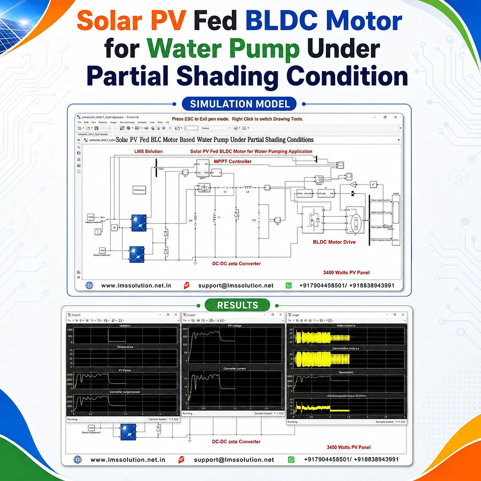
This MATLAB/Simulink model demonstrates a 𝐒𝐨𝐥𝐚𝐫 𝐏𝐕 𝐅𝐞𝐝 𝐁𝐋𝐃𝐂 𝐌𝐨𝐭𝐨𝐫 𝐖𝐚𝐭𝐞𝐫 𝐏𝐮𝐦𝐩 using a 𝐙𝐞𝐭𝐚 𝐜𝐨𝐧𝐯𝐞𝐫𝐭𝐞𝐫 and three selectable MPPT techniques:
𝐇𝐲𝐛𝐫𝐢𝐝 𝐏&𝐎–𝐏𝐒𝐎 𝐌𝐏𝐏𝐓
𝐏𝐒𝐎 𝐌𝐏𝐏𝐓
𝐏&𝐎 𝐌𝐏𝐏𝐓
The system is tested under both 𝐮𝐧𝐢𝐟𝐨𝐫𝐦 𝐢𝐫𝐫𝐚𝐝𝐢𝐚𝐭𝐢𝐨𝐧 and 𝐩𝐚𝐫𝐭𝐢𝐚𝐥 𝐬𝐡𝐚𝐝𝐢𝐧𝐠 conditions to compare the maximum power extraction capability of the different MPPT methods.
𝐒𝐲𝐬𝐭𝐞𝐦 𝐎𝐯𝐞𝐫𝐯𝐢𝐞𝐰
The complete solar-powered water pumping system consists of:
Two solar PV panels connected in series
Irradiance and temperature inputs
Hybrid P&O–PSO MPPT controller
PSO MPPT controller
P&O MPPT controller
MPPT selection logic
PWM generator
MOSFET-based Zeta DC–DC converter
Voltage Source Inverter
BLDC motor drive
Hall sensor-based inverter switching
Water-pump mechanical load
Measurement and monitoring blocks
Main System Parameters
Parameter | Value / Description |
Number of PV panels | 2 |
PV panel connection | Series |
Approximate power per panel | 1700 W |
Total PV rating | Approximately 3400 W |
PV temperature | 25°C |
Uniform irradiance | 1000 W/m² on both panels |
Partial shading irradiance | 500 W/m² on one panel |
Unshaded panel irradiance | 1000 W/m² |
Partial shading transition | After 1 second |
DC–DC converter | Zeta converter |
Motor | BLDC motor |
Application | Water pumping |
MPPT methods | Hybrid P&O–PSO, PSO and P&O |
𝐒𝐲𝐬𝐭𝐞𝐦 𝐀𝐫𝐜𝐡𝐢𝐭𝐞𝐜𝐭𝐮𝐫𝐞
The basic power flow of the system is:
Solar PV Panels → Zeta Converter → Voltage Source Inverter → BLDC Motor → Water Pump
The PV system generates DC power according to the available irradiance.
The MPPT controller continuously uses the measured PV quantities to determine the required converter duty cycle.
The Zeta converter processes the PV output before supplying power to the BLDC motor drive.
The inverter then converts the DC power into the switching waveform required to operate the BLDC motor.
𝐏𝐕 𝐀𝐫𝐫𝐚𝐲 𝐚𝐧𝐝 𝐏𝐚𝐫𝐭𝐢𝐚𝐥 𝐒𝐡𝐚𝐝𝐢𝐧𝐠
Two PV panels are used to demonstrate uniform and non-uniform solar irradiation.
Test Conditions
Operating Condition | Panel 1 Irradiance | Panel 2 Irradiance | Temperature |
Uniform irradiation | 1000 W/m² | 1000 W/m² | 25°C |
Partial shading | 500 W/m² | 1000 W/m² | 25°C |
Under uniform conditions, both PV panels receive the same solar irradiation.
Under partial shading:
One panel remains at 𝐏𝐚𝐧𝐞𝐥 𝟐 = 𝟏𝟎𝟎𝟎 𝐖/𝐦².
The irradiance of 𝐏𝐚𝐧𝐞𝐥 𝟏 drops from 𝟏𝟎𝟎𝟎 𝐖/𝐦² to 𝟓𝟎𝟎 𝐖/𝐦².
The change occurs after approximately 𝐨𝐧𝐞 𝐬𝐞𝐜𝐨𝐧𝐝.
This creates the required partial shading condition for evaluating the MPPT algorithms.
𝐖𝐨𝐫𝐤𝐢𝐧𝐠 𝐏𝐫𝐨𝐜𝐞𝐬𝐬
The simulation operates through the following stages:
The PV panels generate electrical power according to irradiance and temperature.
PV voltage and related electrical quantities are measured.
The selected MPPT algorithm determines the required duty cycle.
The duty cycle is passed to a PWM generator.
PWM pulses control the MOSFET of the Zeta converter.
The converter extracts and regulates the available PV power.
The converter supplies the DC link of the motor drive.
The Voltage Source Inverter drives the BLDC motor.
Hall sensor signals determine the inverter switching sequence.
Motor speed is used to represent the water-pump load characteristic.
PV, converter and motor parameters are monitored during simulation.
𝐙𝐞𝐭𝐚 𝐃𝐂–𝐃𝐂 𝐂𝐨𝐧𝐯𝐞𝐫𝐭𝐞𝐫
A 𝐙𝐞𝐭𝐚 𝐜𝐨𝐧𝐯𝐞𝐫𝐭𝐞𝐫 is connected between the PV array and BLDC motor drive.
Its main functions are to:
Process the power available from the PV array
Operate with voltage conversion capability suitable for changing PV conditions
Receive the duty cycle generated by the MPPT controller
Regulate the power supplied to the motor drive
Support maximum power extraction from the PV panels
The switching MOSFET receives pulses from the PWM generator based on the selected MPPT duty cycle.
𝐂𝐨𝐧𝐭𝐫𝐨𝐥 𝐒𝐭𝐫𝐚𝐭𝐞𝐠𝐲
The model provides three MPPT operating modes through a selection switch.
MPPT Selection Modes
Selection Value | MPPT Mode |
0 | Hybrid P&O–PSO MPPT |
1 | PSO MPPT |
2 | P&O MPPT |
This arrangement makes it possible to evaluate all three algorithms using the same PV array, converter and motor configuration.
𝐇𝐲𝐛𝐫𝐢𝐝 𝐏&𝐎–𝐏𝐒𝐎 𝐌𝐏𝐏𝐓
The proposed hybrid controller combines the characteristics of:
𝐏𝐞𝐫𝐭𝐮𝐫𝐛 𝐚𝐧𝐝 𝐎𝐛𝐬𝐞𝐫𝐯𝐞
𝐏𝐚𝐫𝐭𝐢𝐜𝐥𝐞 𝐒𝐰𝐚𝐫𝐦 𝐎𝐩𝐭𝐢𝐦𝐢𝐳𝐚𝐭𝐢𝐨𝐧
The objective is to improve maximum power tracking when operating conditions change.
From the demonstrated simulation, the hybrid approach provides:
Faster tracking toward the maximum power region
Better response following irradiation changes
Reduced tendency to remain at an unsuitable local operating point
Improved power extraction during partial shading
Better utilization of available solar energy for the BLDC water pump
𝐏𝐒𝐎 𝐌𝐏𝐏𝐓 𝐎𝐩𝐞𝐫𝐚𝐭𝐢𝐨𝐧
In PSO MPPT, the duty cycle is initially explored using different candidate values.
During the initial iterations:
PV power can rise and fall.
Different duty-cycle values are evaluated.
The controller searches for a better operating point.
Several iterations may be required before reaching the desired region.
According to the demonstrated response, PSO can require more time to identify the preferred duty cycle after an irradiance variation.
Under partial shading, the demonstrated PSO response also produces lower extracted PV power than the hybrid controller.
𝐏&𝐎 𝐌𝐏𝐏𝐓 𝐎𝐩𝐞𝐫𝐚𝐭𝐢𝐨𝐧
The P&O controller continuously adjusts the operating point according to changes in PV voltage and power.
The demonstrated simulation shows:
Initial movement toward a power peak
Possibility of settling near a local operating point
Continued oscillation around the tracked point
Longer tracking time compared with the demonstrated hybrid method
These characteristics become particularly important when the PV array operates under non-uniform irradiation.
𝐁𝐋𝐃𝐂 𝐌𝐨𝐭𝐨𝐫 𝐃𝐫𝐢𝐯𝐞
The output of the Zeta converter is supplied to a 𝐕𝐨𝐥𝐭𝐚𝐠𝐞 𝐒𝐨𝐮𝐫𝐜𝐞 𝐈𝐧𝐯𝐞𝐫𝐭𝐞𝐫.
The inverter drives the BLDC motor according to Hall sensor feedback.
The motor-side simulation monitors:
Stator current
Back EMF
Rotor speed
Electromagnetic torque
The available PV power therefore directly influences the operating performance of the BLDC motor and water pump.
𝐖𝐚𝐭𝐞𝐫 𝐏𝐮𝐦𝐩 𝐋𝐨𝐚𝐝
The mechanical load applied to the BLDC motor represents the operating characteristic of a water pump.
The model:
Measures BLDC motor speed
Uses the speed-dependent pump-load characteristic
Generates the corresponding load torque
Applies this mechanical torque to the BLDC motor
This enables the motor to behave as the drive for a water-pumping system rather than as an unloaded motor.
𝐌𝐞𝐚𝐬𝐮𝐫𝐞𝐝 𝐏𝐚𝐫𝐚𝐦𝐞𝐭𝐞𝐫𝐬
Several electrical and mechanical quantities are monitored during simulation.
Section | Parameters Monitored |
PV system | Panel irradiance |
PV system | Temperature |
PV system | PV power |
Converter | Output power |
Converter | Output voltage |
Converter | Output current |
BLDC motor | Stator current |
BLDC motor | Back EMF |
BLDC motor | Speed |
BLDC motor | Electromagnetic torque |
These signals make it possible to examine both the MPPT performance and its effect on motor operation.
𝐒𝐢𝐦𝐮𝐥𝐚𝐭𝐢𝐨𝐧 𝐓𝐞𝐬𝐭 𝟏: 𝐔𝐧𝐢𝐟𝐨𝐫𝐦 𝐈𝐫𝐫𝐚𝐝𝐢𝐚𝐭𝐢𝐨𝐧
For the first test:
Panel 1 irradiance = 𝐨𝐧𝐞 𝐭𝐡𝐨𝐮𝐬𝐚𝐧𝐝 𝐖/𝐦²
Panel 2 irradiance = 𝐨𝐧𝐞 𝐭𝐡𝐨𝐮𝐬𝐚𝐧𝐝 𝐖/𝐦²
Temperature = 𝟐𝟓°𝐂
Total PV rating = approximately 𝟑.𝟒 𝐤𝐖
The same operating condition is evaluated using Hybrid P&O–PSO, PSO and P&O MPPT.
Hybrid P&O–PSO
The PV output approaches the maximum power operating region after the initial transient.
The converter output and BLDC motor responses follow the available PV power.
PSO
The PSO controller initially evaluates different duty-cycle values.
As a result:
Power changes during initial iterations
Several operating points can be observed
Additional time is required before reaching the preferred operating region
P&O
The P&O response moves toward the maximum power region but shows oscillations around the tracked point.
The demonstrated response therefore highlights a slower and more oscillatory tracking process compared with the hybrid approach.
𝐒𝐢𝐦𝐮𝐥𝐚𝐭𝐢𝐨𝐧 𝐓𝐞𝐬𝐭 𝟐: 𝐏𝐚𝐫𝐭𝐢𝐚𝐥 𝐒𝐡𝐚𝐝𝐢𝐧𝐠
The second test introduces a change in irradiance after one second.
Irradiance Profile
Time | Panel 1 | Panel 2 | Condition |
Before 1 s | 1000 W/m² | 1000 W/m² | Uniform irradiation |
After 1 s | 500 W/m² | 1000 W/m² | Partial shading |
The reduction in irradiance on Panel 1 decreases the total available PV power and forces the MPPT controller to search for a new operating point.
𝐒𝐢𝐦𝐮𝐥𝐚𝐭𝐢𝐨𝐧 𝐑𝐞𝐬𝐮𝐥𝐭𝐬
The transcript provides an important comparison under the demonstrated partial shading condition.
MPPT Technique | Observed PV Power Under Partial Shading |
Hybrid P&O–PSO | Approximately 1800 W |
PSO | Approximately 1200 W |
P&O | Exact value not specified |
The hybrid controller therefore extracts approximately:
𝟔𝟎𝟎 𝐖 more power than the demonstrated PSO response under the stated partial shading test.
This difference is significant for a water-pumping system because greater PV power availability can directly support improved motor-drive operation.
𝐇𝐲𝐛𝐫𝐢𝐝 𝐏&𝐎–𝐏𝐒𝐎 𝐯𝐬. 𝐏𝐒𝐎 𝐯𝐬. 𝐏&𝐎
Feature | Hybrid P&O–PSO | PSO | P&O |
Uniform irradiation operation | Supported | Supported | Supported |
Partial shading operation | Supported | Supported | Supported |
Tracking speed in demonstrated model | Faster | Slower after changes | Slower |
Local operating point concern | Reduced in demonstrated response | Can occur | Can occur |
Oscillation around tracked point | Improved response | Depends on iterations | More noticeable |
Partial-shading power reported | ~1800 W | ~1200 W | Not specified |
Main role | Improved tracking | Optimization-based search | Conventional MPPT |
𝐊𝐞𝐲 𝐅𝐞𝐚𝐭𝐮𝐫𝐞𝐬
𝐒𝐨𝐥𝐚𝐫 𝐏𝐕-powered BLDC motor water pumping system
Two series-connected PV panels
Approximately 3.4 kW total PV rating
Uniform and partial shading simulation
Hybrid P&O–PSO MPPT implementation
Independent PSO MPPT mode
Independent P&O MPPT mode
User-selectable MPPT operating modes
Zeta DC–DC converter
PWM-controlled MOSFET switching
Voltage Source Inverter-fed BLDC motor
Hall sensor-based motor commutation
Water-pump mechanical load characteristic
PV power monitoring
Converter voltage and current monitoring
BLDC stator-current monitoring
Back-EMF analysis
Motor-speed analysis
Electromagnetic-torque analysis
Comparative MPPT performance evaluation
𝐖𝐡𝐲 𝐏𝐚𝐫𝐭𝐢𝐚𝐥 𝐒𝐡𝐚𝐝𝐢𝐧𝐠 𝐌𝐚𝐭𝐭𝐞𝐫𝐬
In practical PV installations, all panels do not always receive identical sunlight.
Partial shading can result from:
Clouds
Trees
Nearby structures
Dust accumulation
Uneven panel orientation
Temporary obstructions
When shading occurs, the PV power characteristic becomes more difficult for a conventional MPPT controller to track.
A suitable MPPT technique is therefore especially important for applications such as solar water pumping, where available sunlight directly affects pumping performance.
𝐀𝐝𝐯𝐚𝐧𝐭𝐚𝐠𝐞𝐬 𝐨𝐟 𝐭𝐡𝐞 𝐇𝐲𝐛𝐫𝐢𝐝 𝐌𝐏𝐏𝐓
Based on the demonstrated simulation, the Hybrid P&O–PSO approach offers several benefits:
Improved maximum power extraction
Faster adaptation to irradiance variation
Better response during partial shading
Reduced risk of remaining around an unsuitable local point
Improved utilization of the available PV energy
Effective integration with the Zeta converter
Better power availability for the BLDC water pump
𝐀𝐩𝐩𝐥𝐢𝐜𝐚𝐭𝐢𝐨𝐧𝐬
This type of solar PV-fed BLDC motor drive can be studied for:
Solar-powered irrigation
Agricultural water pumping
Remote water supply
Rural pumping systems
Standalone renewable-energy systems
PV maximum power tracking studies
BLDC motor-drive analysis
Power-electronics control studies
Partial shading analysis
Hybrid MPPT algorithm evaluation
𝐖𝐡𝐨 𝐂𝐚𝐧 𝐔𝐬𝐞 𝐓𝐡𝐢𝐬 𝐌𝐨𝐝𝐞𝐥?
The model is useful for:
Electrical engineering students
Power electronics learners
Renewable-energy researchers
MATLAB/Simulink users
Motor-drive researchers
Solar PV researchers
MPPT algorithm developers
Engineers studying BLDC water-pumping systems
It provides a convenient platform for understanding how changes in PV irradiation affect the entire chain from the 𝐏𝐕 𝐚𝐫𝐫𝐚𝐲 to the 𝐁𝐋𝐃𝐂 𝐦𝐨𝐭𝐨𝐫.
𝐂𝐨𝐧𝐜𝐥𝐮𝐬𝐢𝐨𝐧
The 𝐒𝐨𝐥𝐚𝐫 𝐏𝐕 𝐅𝐞𝐝 𝐁𝐋𝐃𝐂 𝐌𝐨𝐭𝐨𝐫 𝐟𝐨𝐫 𝐖𝐚𝐭𝐞𝐫 𝐏𝐮𝐦𝐩 𝐔𝐧𝐝𝐞𝐫 𝐏𝐚𝐫𝐭𝐢𝐚𝐥 𝐒𝐡𝐚𝐝𝐢𝐧𝐠 𝐂𝐨𝐧𝐝𝐢𝐭𝐢𝐨𝐧 demonstrates how MPPT selection influences the performance of a solar-powered motor-drive system.
The model compares Hybrid P&O–PSO, PSO and P&O MPPT under identical operating conditions. During the demonstrated partial shading test, one PV panel changes from 𝟏𝟎𝟎𝟎 𝐖/𝐦² to 𝟓𝟎𝟎 𝐖/𝐦² after one second while the second panel remains at 𝟏𝟎𝟎𝟎 𝐖/𝐦².
Under this condition, the Hybrid P&O–PSO controller extracts approximately 𝟏𝟖𝟎𝟎 𝐖, whereas the demonstrated PSO response is approximately 𝟏𝟐𝟎𝟎 𝐖. The simulation therefore highlights the benefit of the hybrid MPPT approach for improving solar power extraction and maintaining effective BLDC water-pump operation during changing irradiation conditions.


Comments