


PSO MPPT for Partial Shaded Solar PV System

PSO MPPT for Partial Shaded Solar PV System
𝐈𝐧𝐭𝐫𝐨𝐝𝐮𝐜𝐭𝐢𝐨𝐧
Solar photovoltaic systems normally operate efficiently when all PV modules receive uniform sunlight. However, real-world PV installations often experience partial shading caused by trees, buildings, clouds, dust, or nearby structures.
PSO MPPT for Partial Shaded Solar PV System

Under partial shading conditions:
Different PV modules receive different irradiance levels.
The PV power–voltage characteristic contains several power peaks.
Conventional MPPT techniques may become trapped at a local maximum power point.
Available solar energy may not be fully utilized.
A Particle Swarm Optimization based Maximum Power Point Tracking, or PSO MPPT, controller provides an intelligent way to search for the global maximum power point under these complex operating conditions.
The complete system can be developed and tested using MATLAB/Simulink, making it useful for students, researchers, and engineers working on solar PV control and optimization.
𝐖𝐡𝐚𝐭 𝐈𝐬 𝐏𝐚𝐫𝐭𝐢𝐚𝐥 𝐒𝐡𝐚𝐝𝐢𝐧𝐠 𝐢𝐧 𝐚 𝐒𝐨𝐥𝐚𝐫 𝐏𝐕 𝐒𝐲𝐬𝐭𝐞𝐦?
Partial shading occurs when only some sections of a PV array receive full solar irradiation while other sections receive reduced irradiation.
For example:
PV Section | Irradiance Condition | Effect |
PV Module 1 | 1000 W/m² | High power generation |
PV Module 2 | 300 W/m² | Strongly shaded |
PV Module 3 | 600 W/m² | Partially shaded |
Because the modules operate under different irradiance conditions, the overall PV characteristic becomes more complicated.
Instead of producing a single clear maximum power point, the system can produce:
Multiple local power peaks
One global maximum power point
Rapid changes in the optimum operating point
Reduced output power when incorrect tracking occurs
This is the main reason an optimization-based MPPT technique such as PSO is valuable.
𝐒𝐲𝐬𝐭𝐞𝐦 𝐎𝐯𝐞𝐫𝐯𝐢𝐞𝐰
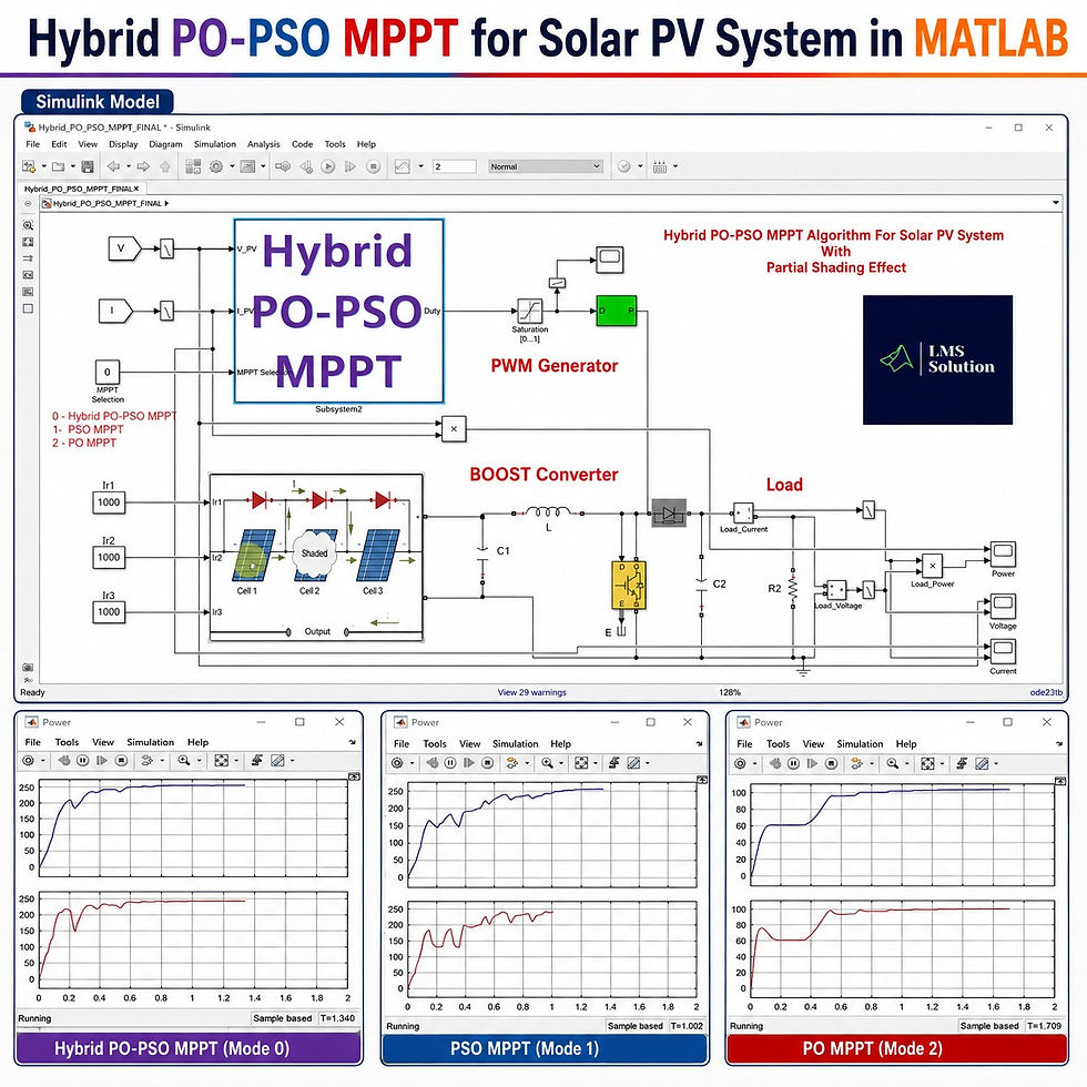
The PSO MPPT controlled solar PV system generally consists of the following sections:
Solar PV array
Irradiance inputs
PV voltage measurement
PV current measurement
PSO MPPT controller
Duty-cycle limiter
PWM generator
Boost converter
DC-link capacitor
Load
Voltage, current, and power monitoring
Basic Power Flow
Solar PV Array → Boost Converter → DC Load
The PSO controller continuously observes the PV operating condition and determines the switching command required to extract maximum available solar power.
𝐌𝐚𝐢𝐧 𝐂𝐨𝐦𝐩𝐨𝐧𝐞𝐧𝐭𝐬
Component | Purpose |
Solar PV Array | Generates electrical power from solar irradiation |
Irradiance Inputs | Create uniform or partial shading conditions |
Voltage Sensor | Measures PV terminal voltage |
Current Sensor | Measures PV current |
PSO MPPT Controller | Searches for the global maximum power point |
Saturation Block | Limits the controller output to a valid range |
PWM Generator | Generates gate pulses for the converter switch |
Boost Converter | Adjusts the operating point and increases DC voltage |
Capacitor | Reduces DC-side voltage ripple |
DC Load | Consumes the generated electrical power |
Scope/Monitoring | Displays voltage, current, and power responses |
𝐖𝐨𝐫𝐤𝐢𝐧𝐠 𝐏𝐫𝐨𝐜𝐞𝐬𝐬
The complete operating process can be understood in a few steps.
1. Solar PV Power Generation
The PV array receives different irradiance levels.
For a partial shading example:
Module 1 receives 1000 W/m²
Module 2 receives 300 W/m²
Module 3 receives 600 W/m²
This creates multiple possible operating points.
2. PV Voltage and Current Measurement
The controller continuously receives:
PV voltage
PV current
These measurements indicate the present operating condition of the solar array.
3. Power Evaluation
The PSO controller checks the power available at different candidate operating points.
Each candidate represents a possible solution for achieving maximum PV power.
4. Particle Movement
The particles change their positions according to their previous performance and the best solution discovered by the swarm.
The search process gradually moves toward the operating point giving the highest PV power.
5. Global Maximum Power Point Identification
The controller compares different candidate solutions and selects the best-performing operating region.
This helps the controller avoid remaining at an incorrect local power peak.
6. Duty-Cycle Generation
The selected PSO output is converted into a suitable converter duty cycle.
A saturation stage can be included to ensure that the duty cycle remains within the allowable operating range.
7. PWM Generation
The duty-cycle command is supplied to the PWM generator.
The PWM signal controls the semiconductor switch of the boost converter.
8. Maximum Power Extraction
By changing the converter switching condition, the PV operating voltage is adjusted until the system operates close to the global maximum power point.
𝐏𝐚𝐫𝐭𝐢𝐜𝐥𝐞 𝐒𝐰𝐚𝐫𝐦 𝐎𝐩𝐭𝐢𝐦𝐢𝐳𝐚𝐭𝐢𝐨𝐧 𝐟𝐨𝐫 𝐌𝐏𝐏𝐓
Particle Swarm Optimization is a population-based optimization technique inspired by the coordinated movement of groups such as bird flocks.
In solar MPPT operation, each particle represents a possible PV operating point.
The algorithm evaluates each particle based on the solar power obtained from that operating point.
Important PSO concepts include:
Particle: One possible operating solution
Population: Group of candidate solutions
Personal best: Best operating condition previously found by a particle
Global best: Best operating condition found by the complete swarm
Iteration: One search cycle of the algorithm
The search continues until the particles converge around the highest-power operating region.
𝐂𝐨𝐧𝐭𝐫𝐨𝐥 𝐒𝐭𝐫𝐚𝐭𝐞𝐠𝐲
The main objective of the control system is to maintain the solar PV array near the global maximum power point even when shading conditions change.
Controller Inputs
The PSO MPPT controller commonly uses:
PV voltage
PV current
Calculated PV power information
Controller Output
The main output is generally:
Converter duty-cycle reference
Controller Sequence
Measure PV Voltage and Current → Evaluate Power → Run PSO Search → Identify Best Particle → Generate Duty Cycle → Produce PWM → Control Boost Converter
This process is repeated during operation.
𝐖𝐡𝐲 𝐂𝐨𝐧𝐯𝐞𝐧𝐭𝐢𝐨𝐧𝐚𝐥 𝐌𝐏𝐏𝐓 𝐂𝐚𝐧 𝐒𝐭𝐫𝐮𝐠𝐠𝐥𝐞 𝐔𝐧𝐝𝐞𝐫 𝐏𝐚𝐫𝐭𝐢𝐚𝐥 𝐒𝐡𝐚𝐝𝐢𝐧𝐠
Traditional MPPT methods are highly effective when the PV curve contains one dominant maximum power point.
Partial shading changes this situation.
The power curve can contain several peaks, such as:
First local maximum
Second local maximum
Additional local maxima
Global maximum
A conventional hill-climbing style controller may detect one local maximum and assume it is the optimum operating point.
This leads to:
Lower harvested solar power
Reduced efficiency
Incorrect operating voltage
Poor utilization of available irradiation
PSO searches across a wider operating region, improving the possibility of locating the true global maximum.
𝐏𝐒𝐎 𝐌𝐏𝐏𝐓 𝐯𝐬 𝐂𝐨𝐧𝐯𝐞𝐧𝐭𝐢𝐨𝐧𝐚𝐥 𝐌𝐏𝐏𝐓
Parameter | Conventional MPPT | PSO MPPT |
Uniform irradiance operation | Good | Good |
Partial shading performance | Limited in some cases | Very suitable |
Local maximum problem | Possible | Significantly reduced |
Global peak search | Limited | Strong |
Algorithm complexity | Low | Moderate |
Computational requirement | Low | Higher |
Adaptability | Moderate | High |
Multiple power peaks | Difficult | Better handling |
Search capability | Local | Global |
MATLAB implementation | Easy | Moderate |
𝐁𝐨𝐨𝐬𝐭 𝐂𝐨𝐧𝐯𝐞𝐫𝐭𝐞𝐫 𝐎𝐩𝐞𝐫𝐚𝐭𝐢𝐨𝐧
The boost converter acts as the interface between the PV array and the DC load.
It normally contains:
Inductor
Semiconductor switch
Diode
Input/output capacitors
PWM control
DC load
The PSO controller does not directly increase the generated solar power.
Instead, it changes the converter operating condition so that the PV array is forced to operate near its optimum voltage and current combination.
Role of Duty Cycle
Changing the duty cycle affects:
PV terminal voltage
PV current
Converter output voltage
Extracted PV power
Therefore, correct duty-cycle selection is essential for successful MPPT operation.
𝐏𝐖𝐌 𝐆𝐞𝐧𝐞𝐫𝐚𝐭𝐢𝐨𝐧
Once the PSO algorithm identifies the desired operating point:
The optimum duty-cycle command is generated.
The command is limited to an acceptable range.
The PWM generator converts the reference into switching pulses.
The pulses control the boost converter switch.
The PV operating point changes accordingly.
The process continues until maximum available power is achieved.
𝐒𝐢𝐦𝐮𝐥𝐚𝐭𝐢𝐨𝐧 𝐒𝐞𝐭𝐮𝐩
A representative partial shading condition can use the following irradiance values:
Parameter | Value |
Irradiance 1 | 1000 W/m² |
Irradiance 2 | 300 W/m² |
Irradiance 3 | 600 W/m² |
MPPT Technique | PSO |
Power Converter | DC–DC Boost Converter |
Control Output | Duty Cycle |
Switching Control | PWM |
Simulation Platform | MATLAB/Simulink |
Operating Condition | Partial Shading |
This irradiance combination intentionally creates non-uniform PV operating conditions for evaluating the MPPT controller.
𝐒𝐢𝐦𝐮𝐥𝐚𝐭𝐢𝐨𝐧 𝐑𝐞𝐬𝐮𝐥𝐭𝐬
The performance of the PSO MPPT system can be evaluated using:
PV voltage response
PV current response
PV output power
Converter output voltage
Converter output current
Duty-cycle variation
Tracking time
Steady-state oscillations
Global peak tracking capability
Typical Response
During the initial search period:
Output power may show several variations.
Particles explore different operating regions.
The duty cycle changes repeatedly.
Power gradually approaches the global maximum.
After convergence:
Output power becomes stable.
Tracking oscillations reduce.
The controller remains near the optimum operating point.
The boost converter supplies stable power to the load.
𝐖𝐡𝐲 𝐭𝐡𝐞 𝐏𝐨𝐰𝐞𝐫 𝐑𝐞𝐬𝐩𝐨𝐧𝐬𝐞 𝐎𝐬𝐜𝐢𝐥𝐥𝐚𝐭𝐞𝐬 𝐃𝐮𝐫𝐢𝐧𝐠 𝐒𝐭𝐚𝐫𝐭𝐮𝐩
Some variation in the initial power response is expected with optimization-based MPPT.
The main reasons include:
Initial particle positions are distributed across the search range.
Different duty-cycle candidates are evaluated.
The controller must distinguish local peaks from the global peak.
Converter dynamics influence the measured power.
The optimization process requires multiple iterations.
Once the global best region is identified, the response should become considerably smoother.
𝐊𝐞𝐲 𝐅𝐞𝐚𝐭𝐮𝐫𝐞𝐬
✅ Global Maximum Power Tracking
PSO is designed to search for the highest available power point rather than simply following the nearest local peak.
✅ Suitable for Partial Shading
The controller can handle different irradiation levels across multiple PV modules.
✅ Intelligent Search Mechanism
Multiple particles explore the PV operating range simultaneously.
✅ Boost Converter Integration
The optimum operating condition is implemented through duty-cycle control of a DC–DC boost converter.
✅ MATLAB/Simulink Implementation
The complete power circuit and control algorithm can be tested in a simulation environment.
✅ Dynamic Irradiance Testing
Different shading conditions can be created easily by changing the irradiance supplied to individual PV modules.
✅ Performance Monitoring
Voltage, current, power, and converter responses can be observed using simulation scopes.
𝐀𝐝𝐯𝐚𝐧𝐭𝐚𝐠𝐞𝐬 𝐨𝐟 𝐏𝐒𝐎 𝐌𝐏𝐏𝐓
Better tracking during partial shading
Improved global search ability
Reduced probability of getting trapped at local maxima
Suitable for nonlinear PV characteristics
Flexible optimization parameters
Can adapt to changing environmental conditions
Easy integration with converter control
Useful for comparison with P&O, Incremental Conductance, fuzzy, ANN, and hybrid MPPT techniques
Can improve harvested PV energy during non-uniform irradiation
𝐋𝐢𝐦𝐢𝐭𝐚𝐭𝐢𝐨𝐧𝐬 𝐨𝐟 𝐏𝐒𝐎 𝐌𝐏𝐏𝐓
Although PSO provides strong global search capability, some practical considerations remain.
Computational complexity is higher than simple conventional MPPT methods.
Initial searching can introduce power oscillations.
Poor PSO parameter selection can slow convergence.
Too many particles can increase computational burden.
Too few particles may reduce search effectiveness.
Rapid environmental changes may require reinitialization or adaptive search logic.
Converter dynamics must be considered while evaluating candidate operating points.
Careful controller tuning is therefore important.
𝐏𝐒𝐎 𝐏𝐚𝐫𝐚𝐦𝐞𝐭𝐞𝐫𝐬 𝐓𝐡𝐚𝐭 𝐀𝐟𝐟𝐞𝐜𝐭 𝐌𝐏𝐏𝐓 𝐏𝐞𝐫𝐟𝐨𝐫𝐦𝐚𝐧𝐜𝐞
PSO Parameter | Influence |
Number of particles | Controls search coverage |
Initial particle positions | Influences initial exploration |
Iteration count | Affects convergence capability |
Inertia setting | Controls exploration behavior |
Personal learning factor | Influences individual particle movement |
Global learning factor | Controls movement toward the best solution |
Duty-cycle limits | Defines allowable converter operating range |
Sampling interval | Determines how frequently the MPPT updates |
Reinitialization condition | Helps respond to major environmental changes |
Proper tuning should balance tracking speed, accuracy, oscillation, and computational effort.
𝐏𝐚𝐫𝐭𝐢𝐚𝐥 𝐒𝐡𝐚𝐝𝐢𝐧𝐠 𝐓𝐞𝐬𝐭 𝐂𝐚𝐬𝐞𝐬
Different shading combinations can be tested to verify controller robustness.
Test Case | PV 1 | PV 2 | PV 3 | Condition |
Case 1 | 1000 W/m² | 1000 W/m² | 1000 W/m² | Uniform irradiation |
Case 2 | 1000 W/m² | 600 W/m² | 300 W/m² | Strong partial shading |
Case 3 | 800 W/m² | 500 W/m² | 1000 W/m² | Unequal irradiation |
Case 4 | 400 W/m² | 1000 W/m² | 700 W/m² | Dynamic shading |
Case 5 | 1000 W/m² | 300 W/m² | 600 W/m² | Multiple-peak evaluation |
Testing several patterns provides a better understanding of global MPPT performance.
𝐏𝐞𝐫𝐟𝐨𝐫𝐦𝐚𝐧𝐜𝐞 𝐏𝐚𝐫𝐚𝐦𝐞𝐭𝐞𝐫𝐬 𝐭𝐨 𝐎𝐛𝐬𝐞𝐫𝐯𝐞
When analyzing the simulation, focus on the following parameters:
Tracking Speed
How quickly the algorithm reaches the global maximum power region.
Tracking Accuracy
How close the extracted power is to the actual available maximum power.
Oscillation Level
The amount of variation in PV power after reaching steady state.
Dynamic Response
How effectively the controller responds when irradiance changes.
Global Peak Detection
Whether the controller correctly identifies the highest peak under multiple-peak conditions.
Converter Stability
Whether the boost converter voltage and current remain stable during MPPT searching.
𝐒𝐢𝐦𝐮𝐥𝐚𝐭𝐢𝐨𝐧 𝐖𝐨𝐫𝐤𝐟𝐥𝐨𝐰 𝐢𝐧 𝐌𝐀𝐓𝐋𝐀𝐁/𝐒𝐢𝐦𝐮𝐥𝐢𝐧𝐤
A simple implementation workflow is:
Create the solar PV array.
Configure individual PV module parameters.
Apply different irradiance values.
Measure PV voltage and current.
Calculate the instantaneous PV power inside the control structure.
Implement the PSO MPPT algorithm.
Define the allowable duty-cycle search range.
Connect the PSO output to a saturation block.
Generate PWM switching pulses.
Build the boost converter.
Connect the DC load.
Measure output voltage, current, and power.
Run the simulation.
Observe initial particle searching.
Verify convergence toward the global maximum power point.
Repeat the test with different shading patterns.
𝐀𝐩𝐩𝐥𝐢𝐜𝐚𝐭𝐢𝐨𝐧𝐬
PSO MPPT can be applied to several solar energy systems, including:
Rooftop solar PV systems
Building-integrated PV systems
Solar-powered DC microgrids
Battery-integrated PV systems
Solar EV charging systems
Grid-connected PV systems
Standalone solar installations
Hybrid renewable energy systems
PV-fed DC motor drives
Solar water pumping systems
PV systems exposed to moving cloud conditions
Large PV arrays experiencing non-uniform irradiation
𝐖𝐡𝐲 𝐔𝐬𝐞 𝐌𝐀𝐓𝐋𝐀𝐁/𝐒𝐢𝐦𝐮𝐥𝐢𝐧𝐤?
MATLAB/Simulink provides an effective platform for studying PSO MPPT because it allows users to combine:
Solar PV modeling
Power electronic converters
Switching devices
PWM generation
Intelligent control algorithms
Dynamic irradiance profiles
Electrical measurements
Data visualization
It also makes it easier to compare multiple MPPT methods under identical operating conditions.
𝐖𝐡𝐨 𝐂𝐚𝐧 𝐔𝐬𝐞 𝐓𝐡𝐢𝐬 𝐌𝐨𝐝𝐞𝐥?
This PSO MPPT solar PV model is useful for:
Electrical engineering students
Power electronics learners
Renewable energy researchers
MATLAB/Simulink users
Control engineers
Solar PV engineers
Researchers studying intelligent MPPT
Engineers working with DC–DC converters
Researchers comparing optimization algorithms
𝐊𝐞𝐲 𝐋𝐞𝐚𝐫𝐧𝐢𝐧𝐠 𝐎𝐮𝐭𝐜𝐨𝐦𝐞𝐬
By studying this system, users can understand:
How partial shading affects solar PV performance
Why multiple maximum power points appear
Difference between local and global maximum power points
How PSO searches for the global optimum
How the duty cycle controls PV operating conditions
How a boost converter interacts with MPPT
How PWM pulses are generated
How irradiance variation affects PV power
How to evaluate MPPT tracking performance
How MATLAB/Simulink can be used for intelligent solar energy control
𝐂𝐨𝐧𝐜𝐥𝐮𝐬𝐢𝐨𝐧
PSO MPPT for Partial Shaded Solar PV System provides an effective solution for extracting maximum available solar power when different PV modules experience unequal irradiation.
The main advantage of PSO is its ability to perform a global search, allowing it to distinguish the true maximum power point from several local maxima created by partial shading.
By integrating PSO MPPT, PWM control, a boost converter, and a solar PV array in MATLAB/Simulink, the system provides a practical platform for analyzing intelligent maximum power point tracking.
Key benefits include:
Effective operation under partial shading
Global maximum power point detection
Improved solar energy utilization
Flexible simulation of different irradiance conditions
Straightforward integration with power electronic converters
Strong potential for advanced renewable energy control research
For solar PV systems exposed to unpredictable shading, Particle Swarm Optimization offers a powerful alternative to conventional MPPT techniques.


Comments