


Model Predictive Speed Control of PMSM in MATLAB/Simulink

Model Predictive Speed Control of PMSM in MATLAB/Simulink
𝐈𝐧𝐭𝐫𝐨𝐝𝐮𝐜𝐭𝐢𝐨𝐧
Model Predictive Control (MPC) is an advanced control technique widely used for achieving fast and accurate dynamic response in electric motor drive systems. In this MATLAB/Simulink implementation, MPC is applied to the speed control of a Permanent Magnet Synchronous Motor (PMSM) and its performance is compared with a conventional PI speed controller.
Model Predictive Speed Control of PMSM
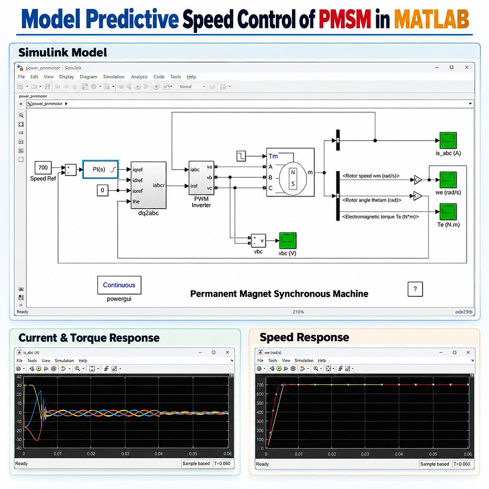
The main objective is to maintain the PMSM at the commanded speed while achieving:
Fast speed tracking
Minimum transient oscillation
Very low or negligible overshoot
Stable steady-state operation
Good response to load-torque variation
Accurate generation of the q-axis current reference
Effective inverter current control
The simulation demonstrates that the MPC-based speed controller provides a faster and smoother response than the conventional PI controller.
𝐒𝐲𝐬𝐭𝐞𝐦 𝐎𝐯𝐞𝐫𝐯𝐢𝐞𝐰
The PMSM drive system consists of the following major sections:
Component | Function |
Speed Reference | Defines the required PMSM operating speed |
Speed Comparator | Calculates the difference between reference and actual speed |
PI / MPC Controller | Generates the required q-axis current reference |
d-axis Reference | Maintained at zero for normal PMSM operation |
dq0-to-abc Transformation | Converts rotating-frame current references into three-phase quantities |
Current Comparator | Compares reference and measured phase currents |
PWM Inverter | Supplies controlled three-phase voltage to the PMSM |
PMSM | Converts electrical energy into mechanical torque and speed |
Speed Measurement | Provides rotor-speed feedback |
Rotor Angle Measurement | Used for coordinate transformation |
Torque Measurement | Measures electromagnetic torque |
Current Measurement | Monitors three-phase stator currents |
The resulting structure forms a closed-loop PMSM speed control system.
𝐌𝐚𝐢𝐧 𝐒𝐢𝐦𝐮𝐥𝐚𝐭𝐢𝐨𝐧 𝐏𝐚𝐫𝐚𝐦𝐞𝐭𝐞𝐫𝐬
The important operating values demonstrated in the model are summarized below.
Parameter | Value / Condition |
Speed reference | 700 |
d-axis current reference | 0 |
Initial load torque | Approximately 3 N·m |
Final load torque | Approximately 1 N·m |
Load-torque change time | 0.04 s |
Simulation duration | Approximately 0.06 s |
Speed transient duration | Approximately 5.5 × 10⁻³ s |
Controller comparison | PI vs MPC |
MPC disturbance input | Not actively considered in this simulation |
The speed signal in the Simulink model is displayed as rad/s.
𝐖𝐨𝐫𝐤𝐢𝐧𝐠 𝐏𝐫𝐨𝐜𝐞𝐬𝐬
The complete control process can be understood in a few simple stages.
1. Speed Reference Generation
A required motor speed is given as the reference input.
In the demonstrated model:
Reference Speed = 700
The PMSM actual rotor speed is continuously measured and fed back to the controller.
2. Speed Error Processing
The controller receives:
Reference speed
Actual PMSM speed
The difference between these signals represents the speed-tracking requirement.
For conventional operation, this signal is processed using a PI speed controller.
For advanced control, the PI controller is replaced by a Model Predictive Controller.
3. Generation of Current Reference
The speed controller generates the important torque-producing current command:
q-axis current reference, iᵩ reference
The d-axis current reference is maintained at:
d-axis current reference = 0
This arrangement is commonly used in PMSM drive control because the q-axis component primarily controls electromagnetic torque.
4. Rotor Position Feedback
The rotor angle of the PMSM is measured continuously.
This rotor-position information is required for the transformation between:
Rotating dq reference frame
Stationary three-phase abc reference frame
Accurate rotor-angle information is therefore important for obtaining proper three-phase current references.
5. dq0-to-abc Current Conversion
The controller produces dq-axis current commands, but the inverter and motor operate using three-phase quantities.
Therefore, the reference currents are transformed into:
Phase-A current reference
Phase-B current reference
Phase-C current reference
These become the three-phase stator current references.
6. Current Comparison
The actual PMSM stator currents are measured as:
iai_a
ibi_b
ici_c
These measured currents are compared with their corresponding reference values.
The current-control stage determines the required inverter switching action.
7. PWM Inverter Control
The generated switching commands are applied to the three-phase PWM inverter.
The inverter supplies the required three-phase electrical power to the PMSM.
By continuously modifying the inverter output, the controller regulates:
Stator current
Electromagnetic torque
Rotor speed
𝐂𝐨𝐧𝐭𝐫𝐨𝐥 𝐒𝐭𝐫𝐚𝐭𝐞𝐠𝐲
𝐂𝐨𝐧𝐯𝐞𝐧𝐭𝐢𝐨𝐧𝐚𝐥 𝐏𝐈 𝐒𝐩𝐞𝐞𝐝 𝐂𝐨𝐧𝐭𝐫𝐨𝐥
Initially, the PMSM is operated using a PI controller.
The PI controller receives the speed error and generates the q-axis current reference.
The basic control flow is:
Speed Reference → Speed Error → PI Controller → q-axis Current Reference → PMSM Drive
The PI controller successfully regulates motor speed, but the transient response can contain:
Initial oscillation
Overshoot
Longer settling behavior
Greater sensitivity to controller tuning
This motivates the use of an advanced predictive controller.
𝐖𝐡𝐲 𝐔𝐬𝐞 𝐌𝐨𝐝𝐞𝐥 𝐏𝐫𝐞𝐝𝐢𝐜𝐭𝐢𝐯𝐞 𝐂𝐨𝐧𝐭𝐫𝐨𝐥?
MPC determines the required controller action by using a mathematical representation of the PMSM drive dynamics.
Rather than responding only to the present error, MPC uses the system model to determine how the motor is expected to respond.
This provides several advantages:
Faster control response
Better transient performance
Reduced overshoot
Improved tracking accuracy
Better handling of system constraints
Systematic controller design
Improved dynamic behavior during operating changes
𝐒𝐲𝐬𝐭𝐞𝐦 𝐈𝐝𝐞𝐧𝐭𝐢𝐟𝐢𝐜𝐚𝐭𝐢𝐨𝐧 𝐟𝐨𝐫 𝐌𝐏𝐂
A suitable plant model is required before designing the MPC controller.
In MATLAB, the PMSM speed-control dynamics can be identified using the System Identification Toolbox.
A typical procedure is:
Operate the PMSM using the existing controller.
Collect appropriate input and output data.
Import the measured signals into the System Identification environment.
Identify the dynamic behavior of the PMSM drive.
Generate a suitable transfer-function model.
Validate the identified model.
Use the identified model for designing the MPC controller.
This allows a complex PMSM drive system to be represented by a model suitable for predictive control design.
𝐌𝐏𝐂 𝐂𝐨𝐧𝐭𝐫𝐨𝐥𝐥𝐞𝐫 𝐈𝐧𝐩𝐮𝐭𝐬 𝐚𝐧𝐝 𝐎𝐮𝐭𝐩𝐮𝐭
The MPC controller used for speed control can be represented as follows.
MPC Signal | Function |
Reference speed | Desired PMSM operating speed |
Actual speed | Measured rotor-speed feedback |
Disturbance input | Optional external disturbance information |
Controller output | q-axis current reference |
In the demonstrated system, the disturbance input is available in the controller structure but is not actively used.
The MPC output becomes the q-axis current reference that controls PMSM torque and consequently regulates motor speed.
𝐌𝐏𝐂-𝐁𝐚𝐬𝐞𝐝 𝐂𝐨𝐧𝐭𝐫𝐨𝐥 𝐅𝐥𝐨𝐰
The overall predictive speed-control sequence is:
Reference Speed
↓
MPC Speed Controller
↓
q-axis Current Reference
↓
dq0-to-abc Transformation
↓
Three-Phase Current References
↓
Current Controller / Comparator
↓
PWM Inverter
↓
PMSM
↓
Rotor Speed Feedback
This closed-loop process is continuously repeated throughout the simulation.
𝐋𝐨𝐚𝐝 𝐓𝐨𝐫𝐪𝐮𝐞 𝐕𝐚𝐫𝐢𝐚𝐭𝐢𝐨𝐧
To examine the PMSM under changing mechanical conditions, the motor is operated with a varying torque command.
The test condition is approximately:
Time Interval | Load Torque |
Initial operating period | 3 N·m |
After 0.04 s | 1 N·m |
This variation helps evaluate whether the speed controller can maintain stable PMSM operation when the mechanical operating condition changes.
A good speed controller should quickly compensate for the change without producing excessive speed fluctuation.
𝐒𝐢𝐦𝐮𝐥𝐚𝐭𝐢𝐨𝐧 𝐑𝐞𝐬𝐮𝐥𝐭𝐬
Several important PMSM signals are observed during simulation.
𝐏𝐌𝐒𝐌 𝐒𝐭𝐚𝐭𝐨𝐫 𝐂𝐮𝐫𝐫𝐞𝐧𝐭
The three-phase stator currents show a comparatively large transient during motor starting.
After the acceleration period:
The currents become balanced.
Their amplitudes reduce as the motor approaches the commanded speed.
The three-phase waveforms maintain the expected phase displacement.
The response changes when the load torque changes.
The initial current variation is associated with the torque required to accelerate the rotor.
𝐄𝐥𝐞𝐜𝐭𝐫𝐨𝐦𝐚𝐠𝐧𝐞𝐭𝐢𝐜 𝐓𝐨𝐫𝐪𝐮𝐞
The PMSM develops a high electromagnetic torque during acceleration.
Once the motor reaches the desired speed:
Torque decreases toward its required operating value.
The controller balances generated torque with mechanical load demand.
A load change produces a corresponding torque response.
The electromagnetic torque therefore closely reflects the dynamic operating condition of the PMSM.
𝐏𝐌𝐒𝐌 𝐒𝐩𝐞𝐞𝐝 𝐑𝐞𝐬𝐩𝐨𝐧𝐬𝐞
The motor starts from zero speed and rapidly accelerates toward the 700 reference level.
The speed reaches the reference region within approximately:
5.5 ms
After the transient period, the motor maintains the required speed with a small steady-state tracking error.
𝐏𝐈 𝐯𝐬 𝐌𝐏𝐂 𝐒𝐩𝐞𝐞𝐝 𝐑𝐞𝐬𝐩𝐨𝐧𝐬𝐞
One of the most important parts of the simulation is the comparison between conventional PI control and MPC.
Performance | PI Controller | Model Predictive Controller |
Speed response | Fast | Very fast |
Initial transient | More noticeable | Reduced |
Overshoot | Can be present | Very small / negligible |
Oscillation | Comparatively higher | Lower |
Speed tracking | Good | Very good |
Settling behavior | Slower | Faster |
Predictive capability | No | Yes |
Model utilization | Not required | Required |
Advanced constraint handling | Limited | Better suited |
The simulation indicates that the MPC-controlled PMSM reaches the desired speed more rapidly while avoiding the noticeable overshoot associated with the conventional controller.
𝐖𝐡𝐲 𝐌𝐏𝐂 𝐏𝐫𝐨𝐯𝐢𝐝𝐞𝐬 𝐁𝐞𝐭𝐭𝐞𝐫 𝐒𝐩𝐞𝐞𝐝 𝐂𝐨𝐧𝐭𝐫𝐨𝐥
The improvement occurs because the MPC controller does not depend only on instantaneous speed error.
It uses the identified PMSM drive model to determine the most suitable control action.
As a result, it can:
Anticipate future system behavior
Correct speed deviations rapidly
Reduce aggressive control action
Improve transient damping
Maintain the reference speed more smoothly
Provide improved performance during changing load conditions
This makes MPC particularly attractive for high-performance PMSM drive applications.
𝐊𝐞𝐲 𝐅𝐞𝐚𝐭𝐮𝐫𝐞𝐬
Model Predictive Control of PMSM speed
MATLAB/Simulink implementation
Closed-loop rotor-speed feedback
PMSM dq-axis current control
q-axis current reference generation
Zero d-axis reference operation
dq0-to-abc transformation
Three-phase PWM inverter
Rotor-angle feedback
Stator-current measurement
Electromagnetic torque monitoring
Variable load-torque testing
System Identification based plant modeling
Direct comparison between PI and MPC
Fast reference-speed tracking
Reduced transient overshoot
𝐀𝐩𝐩𝐥𝐢𝐜𝐚𝐭𝐢𝐨𝐧𝐬
MPC-based PMSM speed control can be applied in many advanced electrical drive systems, including:
Electric vehicle traction drives
Industrial servo drives
Robotics
CNC machine drives
Automated manufacturing systems
Electric propulsion
High-performance motor drives
Renewable-energy drive systems
Industrial automation
Compressor and pump drives
Aerospace actuators
Smart manufacturing systems
𝐀𝐝𝐯𝐚𝐧𝐭𝐚𝐠𝐞𝐬 𝐨𝐟 𝐌𝐏𝐂 𝐟𝐨𝐫 𝐏𝐌𝐒𝐌
𝐅𝐚𝐬𝐭 𝐃𝐲𝐧𝐚𝐦𝐢𝐜 𝐑𝐞𝐬𝐩𝐨𝐧𝐬𝐞
The motor can reach the required reference speed more rapidly.
𝐋𝐨𝐰 𝐎𝐯𝐞𝐫𝐬𝐡𝐨𝐨𝐭
MPC can produce a smoother speed transition with very low overshoot.
𝐈𝐦𝐩𝐫𝐨𝐯𝐞𝐝 𝐓𝐫𝐚𝐜𝐤𝐢𝐧𝐠
The actual PMSM speed closely follows the commanded reference.
𝐁𝐞𝐭𝐭𝐞𝐫 𝐓𝐫𝐚𝐧𝐬𝐢𝐞𝐧𝐭 𝐂𝐨𝐧𝐭𝐫𝐨𝐥
Speed oscillations during acceleration can be reduced.
𝐏𝐫𝐞𝐝𝐢𝐜𝐭𝐢𝐯𝐞 𝐎𝐩𝐞𝐫𝐚𝐭𝐢𝐨𝐧
The controller considers the predicted behavior of the PMSM before selecting its control action.
𝐀𝐝𝐯𝐚𝐧𝐜𝐞𝐝 𝐂𝐨𝐧𝐭𝐫𝐨𝐥 𝐅𝐥𝐞𝐱𝐢𝐛𝐢𝐥𝐢𝐭𝐲
MPC can be expanded to incorporate operating limits, disturbances, and additional control objectives.
𝐏𝐈 𝐂𝐨𝐧𝐭𝐫𝐨𝐥𝐥𝐞𝐫 𝐨𝐫 𝐌𝐏𝐂 — 𝐖𝐡𝐢𝐜𝐡 𝐈𝐬 𝐁𝐞𝐭𝐭𝐞𝐫?
A PI controller remains attractive when:
Simple implementation is required
Computational requirements must be low
Motor operating conditions are relatively constant
Basic speed regulation is sufficient
MPC becomes more attractive when:
Very fast speed response is required
Overshoot needs to be minimized
High dynamic performance is important
Plant dynamics are available
System constraints need to be considered
The PMSM operates under rapidly changing conditions
For this simulation, MPC provides the superior speed transient response.
𝐌𝐀𝐓𝐋𝐀𝐁/𝐒𝐢𝐦𝐮𝐥𝐢𝐧𝐤 𝐓𝐨𝐨𝐥𝐬 𝐔𝐬𝐞𝐝
A typical implementation may use:
MATLAB
Simulink
Simscape Electrical
Permanent Magnet Synchronous Machine model
PWM inverter
System Identification Toolbox
Model Predictive Control Toolbox
Scope blocks
Current and voltage measurement blocks
Rotor-speed and electromagnetic-torque measurements
These tools provide a convenient environment for modeling, controller design, simulation, and performance comparison.
𝐖𝐡𝐚𝐭 𝐂𝐚𝐧 𝐁𝐞 𝐎𝐛𝐬𝐞𝐫𝐯𝐞𝐝 𝐅𝐫𝐨𝐦 𝐭𝐡𝐞 𝐑𝐞𝐬𝐮𝐥𝐭𝐬?
The most important observations are:
PMSM speed starts from zero.
The motor rapidly accelerates toward the commanded speed.
The reference value is approximately 700.
High starting torque is produced during acceleration.
Stator currents show a larger transient during startup.
Motor current stabilizes after the speed settles.
Load torque is changed during the simulation.
The conventional PI controller regulates the speed successfully.
PI control exhibits a more noticeable transient response.
MPC reaches the speed reference more rapidly.
MPC produces significantly lower overshoot.
The PMSM maintains stable speed after reaching the required operating point.
𝐂𝐨𝐧𝐜𝐥𝐮𝐬𝐢𝐨𝐧
Model Predictive Speed Control of PMSM in MATLAB/Simulink provides an effective method for improving the dynamic performance of a permanent magnet synchronous motor drive.
The PMSM speed is controlled through the q-axis current reference, while the d-axis reference is maintained at zero. The current references are converted into three-phase quantities and used to control the PWM inverter supplying the motor.
A dynamic model of the PMSM speed-control system is identified and used for MPC design. When compared with the conventional PI controller, the Model Predictive Controller demonstrates faster speed tracking, lower oscillation, negligible overshoot, and improved transient performance.
This simulation is particularly useful for students, researchers, and engineers who want to understand PMSM speed control, model predictive control, system identification, field-oriented current control, and MATLAB/Simulink motor-drive simulation.


Comments