


MATLAB Simulation of Single Phase Shunt Active Filter

MATLAB Simulation of Single Phase Shunt Active Filter
𝐈𝐧𝐭𝐫𝐨𝐝𝐮𝐜𝐭𝐢𝐨𝐧
A Single Phase Shunt Active Filter is an effective power-quality solution for reducing current harmonics produced by nonlinear loads. When a nonlinear load is connected to an AC supply, the load current becomes distorted and contains significant harmonic components.
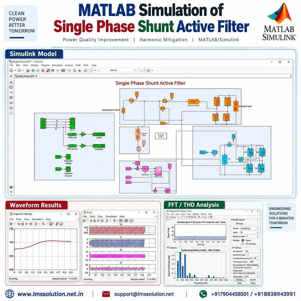
This MATLAB/Simulink model demonstrates how a Single Phase Shunt Active Power Filter (SAPF) can:
Reduce source-current harmonics
Compensate nonlinear load current
Supply the required compensating current
Improve the source-current waveform
Maintain the DC-link capacitor voltage
Reduce Total Harmonic Distortion (THD)
Improve overall power quality
The system uses a single-phase H-bridge voltage-source inverter, DC-link capacitor, coupling inductor, and p–q-based control strategy to generate the required compensating current.
𝐒𝐲𝐬𝐭𝐞𝐦 𝐎𝐯𝐞𝐫𝐯𝐢𝐞𝐰
The MATLAB/Simulink model consists of the following major sections:
Component | Function |
Single-phase AC source | Supplies electrical power to the system |
Source inductor | Represents source-side inductance |
Nonlinear load | Produces distorted load current and harmonics |
H-bridge inverter | Generates compensating current |
DC-link capacitor | Provides energy support for active-filter operation |
Coupling inductor | Connects the active filter to the AC system |
Voltage and current measurement | Measures source, load, and filter quantities |
PI controller | Regulates the DC-link capacitor voltage |
p–q control | Generates the compensating-current reference |
Current controller | Produces switching commands for the inverter |
The nonlinear load contains a bridge rectifier and inductive RL load, resulting in a highly distorted load-current waveform.
𝐖𝐡𝐲 𝐢𝐬 𝐚 𝐒𝐡𝐮𝐧𝐭 𝐀𝐜𝐭𝐢𝐯𝐞 𝐅𝐢𝐥𝐭𝐞𝐫 𝐍𝐞𝐞𝐝𝐞𝐝?
Ideally, the current drawn from an AC source should be nearly sinusoidal.
However, when a nonlinear load such as a rectifier is connected:
Load current becomes non-sinusoidal.
Harmonic current increases.
Source-current quality deteriorates.
Additional reactive and harmonic current flows through the supply.
Other loads connected to the same supply may experience degraded power quality.
The shunt active filter is connected in parallel with the system to compensate for these unwanted current components.
Instead of forcing the source to supply the entire distorted current, the active filter injects an appropriate compensating current.
As a result:
Source current ≈ sinusoidal current
while the nonlinear load can continue drawing its required distorted current.
𝐖𝐨𝐫𝐤𝐢𝐧𝐠 𝐏𝐫𝐨𝐜𝐞𝐬𝐬
The overall operation can be understood in a few simple steps.
1. Nonlinear Load Draws Distorted Current
The bridge-rectifier-based nonlinear load draws a non-sinusoidal current from the AC system.
Therefore:
Source voltage remains nearly sinusoidal.
Load current contains significant harmonics.
Source current becomes distorted when no compensation is provided.
2. System Quantities Are Measured
The controller continuously monitors important electrical signals such as:
Source voltage
Load current
Source current
Active-filter current
DC-link capacitor voltage
These signals are used by the active-filter control system.
3. Reference Compensating Current Is Generated
The control system determines how much current must be injected by the active filter.
The calculated reference current represents the compensation required for:
Harmonic current
Reactive-current component
Converter losses
4. Active Filter Generates Compensation Current
The H-bridge inverter produces the required filter current.
This current is injected into the point of connection through the coupling inductor.
The active filter therefore supplies much of the unwanted current demanded by the nonlinear load.
5. Source Current Becomes Nearly Sinusoidal
Once the compensation current is properly injected:
Load current remains distorted.
Filter current contains the compensating components.
Source current becomes much closer to a sine wave.
Source-current THD is substantially reduced.
This clearly demonstrates the harmonic-compensation capability of the shunt active filter.
𝐂𝐨𝐧𝐭𝐫𝐨𝐥 𝐒𝐭𝐫𝐚𝐭𝐞𝐠𝐲
The active-filter controller contains two major control functions:
DC-link voltage regulation
Reference current generation
DC-Link Voltage Control
The DC-link capacitor voltage is compared with its reference value.
For this simulation:
Parameter | Value |
DC-link voltage reference | 700 V |
Fundamental frequency | 50 Hz |
The voltage error is processed using a PI controller.
The PI controller generates a loss-power component that compensates for power losses associated with the inverter and filter operation.
This control action keeps the capacitor voltage close to its specified reference.
𝐩–𝐪 𝐁𝐚𝐬𝐞𝐝 𝐂𝐨𝐧𝐭𝐫𝐨𝐥
The model applies a p–q-based power-control concept for reference-current generation.
Because the actual system is single phase, additional phase-shifted signals are generated from the measured voltage and current so that the control algorithm can process the signals in an equivalent multi-axis form.
The control sequence includes:
Measurement of source voltage
Measurement of nonlinear load current
Generation of phase-shifted voltage signals
Generation of phase-shifted current signals
Separation of control quantities
Calculation of active and reactive power components
Filtering of the active-power component
Addition of converter loss compensation
Generation of active-filter reference current
This reference current determines how the shunt active filter should operate.
𝐋𝐨𝐰-𝐏𝐚𝐬𝐬 𝐅𝐢𝐥𝐭𝐞𝐫 𝐎𝐩𝐞𝐫𝐚𝐭𝐢𝐨𝐧
The calculated instantaneous active-power signal contains both:
Average component
Oscillating component
A low-pass filter is used to extract the required average component.
The resulting signal is combined with the loss component generated by the DC-link voltage controller.
This information is then used for compensating-current reference generation.
𝐂𝐮𝐫𝐫𝐞𝐧𝐭 𝐂𝐨𝐧𝐭𝐫𝐨𝐥
The generated reference current is compared with the actual shunt-active-filter current.
The current-controller error is then used to produce switching signals for the H-bridge inverter.
The inverter continuously adjusts its output current so that the actual compensating current follows the reference current.
The main objective is:
Supply harmonic current from the active filter
Supply the required compensation component
Prevent these unwanted components from being drawn directly from the source
𝐃𝐂-𝐋𝐢𝐧𝐤 𝐂𝐚𝐩𝐚𝐜𝐢𝐭𝐨𝐫 𝐕𝐨𝐥𝐭𝐚𝐠𝐞
At the beginning of the simulation, the capacitor voltage is below the reference.
The controller gradually charges the capacitor toward the specified:
700 V DC-link reference
The simulation waveform shows the voltage increasing and settling around the reference region.
This confirms proper operation of the DC-link voltage-regulation loop.
𝐒𝐢𝐦𝐮𝐥𝐚𝐭𝐢𝐨𝐧 𝐑𝐞𝐬𝐮𝐥𝐭𝐬
The simulation clearly shows three different current characteristics.
Signal | Observed Nature |
Source voltage | Sinusoidal |
Load current | Highly distorted/non-sinusoidal |
Active-filter current | Compensating and harmonic-rich |
Source current with SAPF | Nearly sinusoidal |
The active-filter current is intentionally non-sinusoidal because it contains the components required to cancel the harmonic content of the load current from the source side.
𝐓𝐇𝐃 𝐀𝐧𝐚𝐥𝐲𝐬𝐢𝐬
FFT analysis is used to evaluate the harmonic performance of the system.
Representative values observed during the simulations include:
Operating Condition | Approximate THD |
Nonlinear load current | 44.79% |
Load THD displayed in another simulation run | ≈46.65% |
Source current without active filter | ≈46% |
Source current with active filter | ≈0.47–0.58% under the shown FFT settings |
Active-filter compensation current | ≈119.3% |
The exact displayed THD can vary with the FFT analysis window, selected maximum frequency, and simulation operating point.
The main result is clear:
The source-current harmonic distortion is reduced substantially after connecting the shunt active filter.
𝐇𝐚𝐫𝐦𝐨𝐧𝐢𝐜 𝐒𝐩𝐞𝐜𝐭𝐫𝐮𝐦
The FFT window also allows individual harmonic components to be examined.
Representative values shown in the simulation include:
Harmonic Component | Approximate Magnitude |
3rd harmonic | ≈0.5% |
5th harmonic | Very small |
7th harmonic | ≈0.06% |
Overall source-current THD | ≈0.58% |
The source-current fundamental magnitude is approximately:
6.88 A
The low harmonic amplitudes confirm that the compensated source current is much closer to a sinusoidal waveform.
𝐖𝐢𝐭𝐡𝐨𝐮𝐭 𝐒𝐡𝐮𝐧𝐭 𝐀𝐜𝐭𝐢𝐯𝐞 𝐅𝐢𝐥𝐭𝐞𝐫
The active filter can be disconnected to understand its effect.
When the SAPF is disconnected:
No compensating current is injected.
Source current follows the nonlinear load current.
Both source current and load current become highly distorted.
Source-current THD approaches the nonlinear-load THD.
Quantity | Without SAPF |
Load current | Non-sinusoidal |
Source current | Non-sinusoidal |
Load THD | ≈46% |
Source THD | ≈46% |
Harmonic compensation | Not available |
This comparison clearly demonstrates why active harmonic compensation is required.
𝐖𝐢𝐭𝐡 𝐒𝐡𝐮𝐧𝐭 𝐀𝐜𝐭𝐢𝐯𝐞 𝐅𝐢𝐥𝐭𝐞𝐫
After reconnecting the shunt active filter:
The inverter generates compensation current.
Harmonic components required by the nonlinear load are largely supplied by the filter.
The source supplies a much cleaner current.
Source current becomes nearly sinusoidal.
THD is significantly reduced.
Parameter | Without SAPF | With SAPF |
Load-current waveform | Distorted | Distorted |
Source-current waveform | Distorted | Nearly sinusoidal |
Load-current THD | ≈45–46% | ≈45–46% |
Source-current THD | ≈46% | As low as ≈0.47–0.58% in the displayed FFT analysis |
Compensation current | No | Yes |
DC-link regulation | Not applicable | Around 700 V reference |
The load current itself does not need to become sinusoidal. The important objective is to prevent its harmonic components from propagating into the source current.
𝐊𝐞𝐲 𝐅𝐞𝐚𝐭𝐮𝐫𝐞𝐬
Single-phase shunt active power filter simulation
MATLAB/Simulink-based analysis
Nonlinear bridge-rectifier load
H-bridge voltage-source inverter
DC-link capacitor regulation
700 V DC-link reference
PI-based DC voltage controller
p–q-based reference-current generation
Coupling-inductor connection
Harmonic-current compensation
Reactive-current compensation
Source-current waveform improvement
FFT harmonic analysis
THD comparison with and without active filtering
𝐀𝐩𝐩𝐥𝐢𝐜𝐚𝐭𝐢𝐨𝐧𝐬
Single-phase shunt active filters can be useful in electrical systems containing nonlinear loads such as:
Rectifier-fed loads
Power electronic converters
Variable electronic loads
Computer and electronic power supplies
UPS systems
Battery chargers
Single-phase industrial loads
Power-quality compensation systems
Renewable-energy interfacing systems
Distribution-level harmonic mitigation
𝐖𝐡𝐚𝐭 𝐂𝐚𝐧 𝐁𝐞 𝐋𝐞𝐚𝐫𝐧𝐞𝐝 𝐟𝐫𝐨𝐦 𝐓𝐡𝐢𝐬 𝐒𝐢𝐦𝐮𝐥𝐚𝐭𝐢𝐨𝐧?
This model is useful for understanding:
How nonlinear loads create harmonics
Why source current becomes distorted
How a shunt active filter compensates harmonic current
The role of the DC-link capacitor
PI-based capacitor-voltage regulation
Reference-current generation
H-bridge inverter control
Coupling-inductor operation
FFT analysis in MATLAB/Simulink
THD comparison before and after compensation
𝐊𝐞𝐲 𝐑𝐞𝐬𝐮𝐥𝐭
The most important observation from the simulation is:
Nonlinear load current remains distorted, while the source current becomes nearly sinusoidal after activation of the shunt active filter.
The FFT results demonstrate a substantial reduction in source-current THD from approximately 46% without compensation to a much lower level after compensation, reaching approximately 0.47–0.58% under the displayed FFT analysis settings.
𝐂𝐨𝐧𝐜𝐥𝐮𝐬𝐢𝐨𝐧
The MATLAB Simulation of Single Phase Shunt Active Filter demonstrates an effective method for improving power quality in a single-phase system supplying a nonlinear load.
The nonlinear load produces a highly distorted current with significant harmonic content. The shunt active filter detects the required compensation and injects an appropriate current through the H-bridge inverter and coupling inductor.
The simulation demonstrates:
Significant harmonic-current compensation
Nearly sinusoidal source current
Reduced source-current THD
DC-link capacitor regulation around 700 V
Effective operation of the PI and p–q-based control system
Clear improvement in source-side power quality
This MATLAB/Simulink model is particularly useful for students, researchers, and power-electronics engineers studying active power filters, harmonic mitigation, nonlinear loads, current compensation, FFT analysis, and power-quality improvement.


Comments