


MATLAB Simulation of Zeta Converter Fed BLDC Motor for Power Factor Correction and Speed Control

MATLAB Simulation of Zeta Converter Fed BLDC Motor for Power Factor Correction and Speed Control
𝐈𝐧𝐭𝐫𝐨𝐝𝐮𝐜𝐭𝐢𝐨𝐧
The Zeta converter-fed BLDC motor drive is a useful configuration for applications that require both speed control and improved input power factor.
In this MATLAB/Simulink model, a single-phase AC supply is converted into DC using a diode rectifier. A Zeta DC–DC converter regulates the DC-link voltage, while a voltage source inverter drives the BLDC motor.
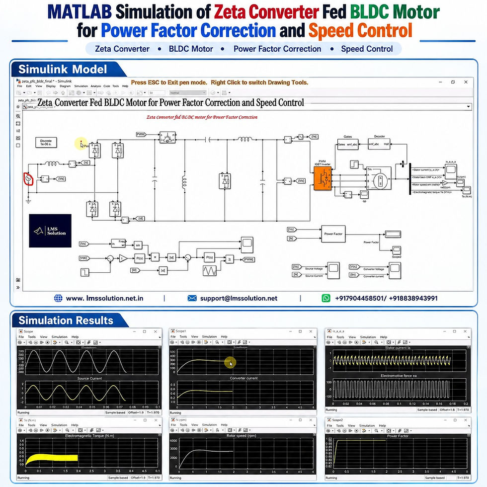
The main objectives of the simulation are to:
Maintain the input current close to a sinusoidal waveform
Achieve a near-unity power factor
Regulate the Zeta converter output voltage
Control the BLDC motor speed
Maintain stable operation during reference-voltage changes
Maintain stable operation during sudden load changes
𝐒𝐲𝐬𝐭𝐞𝐦 𝐎𝐯𝐞𝐫𝐯𝐢𝐞𝐰
The complete system contains the following main sections:
Section | Function |
Single-phase AC source | Supplies input electrical power |
Input-side filter | Reduces unwanted input-side disturbances |
Diode rectifier | Converts AC voltage into DC |
Capacitive filtering stage | Smooths the rectified DC waveform |
Zeta converter | Regulates DC output voltage and supports power factor correction |
Voltage source inverter | Converts DC into controlled three-phase supply |
BLDC motor | Converts electrical energy into mechanical energy |
Hall sensor decoder | Determines rotor position |
Gate pulse logic | Generates inverter switching signals |
Outer voltage loop | Controls Zeta converter output voltage |
Inner current loop | Shapes input current for power factor correction |
Power factor measurement | Monitors source-side power factor |
𝐏𝐨𝐰𝐞𝐫 𝐅𝐥𝐨𝐰 𝐢𝐧 𝐭𝐡𝐞 𝐒𝐲𝐬𝐭𝐞𝐦
The electrical power passes through the system in the following sequence:
Single-Phase AC Source → Diode Rectifier → Zeta Converter → Voltage Source Inverter → BLDC Motor
The control system operates alongside this power circuit to regulate both the converter and motor operation.
𝐖𝐡𝐲 𝐏𝐨𝐰𝐞𝐫 𝐅𝐚𝐜𝐭𝐨𝐫 𝐂𝐨𝐫𝐫𝐞𝐜𝐭𝐢𝐨𝐧 𝐈𝐬 𝐑𝐞𝐪𝐮𝐢𝐫𝐞𝐝
A diode bridge rectifier behaves as a nonlinear load from the AC supply point of view.
Without proper current control:
Source current may become distorted.
The input current may no longer remain sinusoidal.
Harmonic content can increase.
Input power quality can deteriorate.
Power factor may reduce.
The power factor correction controller therefore modifies the converter operation so that the input current follows the source-voltage waveform more closely.
The desired condition is:
Sinusoidal source voltage
Nearly sinusoidal source current
Very small phase difference between voltage and current
Power factor close to unity
𝐖𝐨𝐫𝐤𝐢𝐧𝐠 𝐏𝐫𝐨𝐜𝐞𝐬𝐬
1. AC-to-DC Conversion
The single-phase AC source is connected to a diode bridge rectifier.
The rectifier converts the AC input into a rectified DC quantity before supplying the Zeta converter stage.
2. Zeta Converter Operation
The Zeta converter is used to control the DC voltage supplied to the inverter.
Its switching operation is controlled according to:
Required DC output voltage
Measured converter voltage
Input current condition
Power factor correction requirement
Changing the Zeta converter duty cycle changes its output voltage.
This regulated voltage is then supplied to the inverter.
3. Voltage Source Inverter
The regulated DC output of the Zeta converter is connected to the voltage source inverter.
The inverter provides the required electrical excitation for the BLDC motor.
Its gate signals are generated according to rotor-position information obtained from the motor Hall sensors.
4. BLDC Motor Commutation
The BLDC motor uses Hall sensor signals to identify rotor position.
The Hall signals are processed by the decoder and converted into the required inverter switching pattern.
This allows correct electronic commutation of the BLDC motor.
𝐂𝐨𝐧𝐭𝐫𝐨𝐥 𝐒𝐭𝐫𝐚𝐭𝐞𝐠𝐲
The power factor correction system uses a two-loop control structure.
Outer Voltage Control Loop
The outer loop regulates the Zeta converter DC output voltage.
The control sequence is:
Reference DC Voltage → Voltage Comparison → PI Controller → Reference Current Magnitude
The measured converter voltage is compared with the desired reference.
The resulting voltage error is processed using a PI controller.
The controller output determines the required reference-current magnitude.
Inner Current Control Loop
The inner loop controls the rectifier-side current so that the AC source current remains close to sinusoidal.
The control structure uses:
Source voltage measurement
PLL-based phase detection
Sinusoidal reference generation
Reference current magnitude
Rectifier-current feedback
PI current controller
PWM generation
Zeta converter switching
This inner current loop is the main section responsible for power factor correction.
𝐏𝐋𝐋-𝐁𝐚𝐬𝐞𝐝 𝐑𝐞𝐟𝐞𝐫𝐞𝐧𝐜𝐞 𝐆𝐞𝐧𝐞𝐫𝐚𝐭𝐢𝐨𝐧
The source voltage is measured and processed using a phase-locked loop.
The PLL provides the electrical phase information required to generate a sinusoidal reference.
The generated sinusoidal waveform is then multiplied by the current-reference magnitude obtained from the voltage controller.
This produces the required current reference for the inner control loop.
𝐂𝐮𝐫𝐫𝐞𝐧𝐭 𝐂𝐨𝐧𝐭𝐫𝐨𝐥 𝐚𝐧𝐝 𝐏𝐖𝐌 𝐆𝐞𝐧𝐞𝐫𝐚𝐭𝐢𝐨𝐧
The reference current is compared with the measured rectifier current.
The current error is processed using another PI controller.
The controller produces the converter duty-cycle command.
This command is compared with a triangular carrier waveform to generate the PWM gate pulse for the Zeta converter switch.
By continuously adjusting the duty cycle:
Converter output voltage is regulated.
Rectifier current is controlled.
Source current becomes approximately sinusoidal.
Power factor is improved.
𝐊𝐞𝐲 𝐒𝐢𝐦𝐮𝐥𝐚𝐭𝐢𝐨𝐧 𝐏𝐚𝐫𝐚𝐦𝐞𝐭𝐞𝐫𝐬
Parameter | Value / Condition |
Initial DC voltage reference | 250 V |
Changed DC voltage reference | 150 V |
Reference voltage change time | 2 s |
Initial motor load torque | 0 N·m |
Changed motor load torque | 0.5 N·m |
Load change time | 3.5 s |
Converter current before load change | Approximately 0.3 A |
Converter current after load change | Approximately 0.8 A |
Power factor during normal operation | Near 1 |
Temporary power factor during voltage transition | Approximately 0.96–0.98 |
𝐒𝐢𝐦𝐮𝐥𝐚𝐭𝐢𝐨𝐧 𝐓𝐞𝐬𝐭 𝐂𝐨𝐧𝐝𝐢𝐭𝐢𝐨𝐧𝐬
The model is evaluated under two important dynamic operating conditions.
Test 1: Reference Voltage Change
At 2 seconds, the converter voltage reference changes from:
250 V → 150 V
This test evaluates:
DC-link voltage regulation
Converter transient response
Input-current waveform
Power factor performance
Motor operating response
Test 2: Motor Load Change
At approximately 3.5 seconds, motor load torque changes from:
0 N·m → 0.5 N·m
This test checks whether the controller can maintain stable operation when the mechanical load suddenly increases.
𝐒𝐢𝐦𝐮𝐥𝐚𝐭𝐢𝐨𝐧 𝐑𝐞𝐬𝐮𝐥𝐭𝐬
Source Voltage and Source Current
The source voltage and current waveforms show that:
Source current remains approximately sinusoidal.
Source voltage and current remain closely aligned.
The phase difference between them is very small.
The power factor remains close to unity.
This confirms the operation of the input-side power factor correction control.
Converter Voltage Response
Initially, the DC voltage reference is set to 250 V.
The Zeta converter output rises and settles close to the reference value.
At 2 seconds, the reference is reduced to 150 V.
After the change:
Converter voltage decreases toward the new reference.
A transient appears during the transition.
The controller subsequently restores voltage regulation.
The output settles close to 150 V.
Power Factor Response
Under steady operation, the measured power factor remains close to 1.
During the sudden reference-voltage transition, the power factor temporarily decreases to approximately:
0.98
0.96
After the transient period, it increases again toward unity.
This shows that the power factor correction controller continues operating even during DC-voltage changes.
BLDC Motor Speed
The BLDC motor speed follows the operating condition established by the regulated converter voltage and inverter switching system.
When the DC voltage changes, the motor operating point also changes accordingly.
The motor speed waveform demonstrates the relationship between:
Zeta converter output voltage
Inverter input voltage
BLDC motor operating speed
Electromagnetic Torque
The electromagnetic torque waveform shows the motor response during:
Starting
Steady-state operation
Reference-voltage variation
Mechanical load variation
Some torque ripple is naturally present because of the electronic commutation of the BLDC motor.
Stator Current and Back EMF
The simulation also displays:
BLDC stator current
Motor back EMF
These waveforms help verify the electrical commutation and motor operating characteristics.
𝐑𝐞𝐬𝐩𝐨𝐧𝐬𝐞 𝐃𝐮𝐫𝐢𝐧𝐠 𝐋𝐨𝐚𝐝 𝐂𝐡𝐚𝐧𝐠𝐞
When the motor torque changes from 0 to 0.5 N·m:
Motor power demand increases.
Converter current increases.
Converter current changes from approximately 0.3 A to 0.8 A.
DC voltage temporarily decreases.
The voltage controller restores the DC voltage toward 150 V.
Source current remains approximately sinusoidal.
Power factor remains close to unity.
This demonstrates the response of the cascaded voltage-current control structure under a sudden motor-load disturbance.
𝐑𝐞𝐬𝐮𝐥𝐭 𝐒𝐮𝐦𝐦𝐚𝐫𝐲
Operating Condition | Observed Response |
Normal operation | Stable converter and motor operation |
250 V reference | Output voltage tracks approximately 250 V |
250 V → 150 V reference change | Voltage settles toward the new reference |
Voltage-transition period | Temporary reduction in power factor |
After voltage settling | Power factor returns near unity |
Source current | Approximately sinusoidal |
Voltage-current phase difference | Very small |
0 → 0.5 N·m load change | Converter current increases |
Load disturbance | Temporary DC voltage reduction |
After disturbance | DC voltage returns close to reference |
Steady-state power factor | Near unity |
𝐊𝐞𝐲 𝐅𝐞𝐚𝐭𝐮𝐫𝐞𝐬
Zeta converter-based BLDC motor drive
Single-phase AC input
Diode bridge rectifier
Closed-loop DC voltage regulation
Power factor correction
Dual-loop voltage and current control
PI-controller-based control
PLL-based sinusoidal reference generation
PWM switching control
Hall sensor-based BLDC commutation
Voltage source inverter
Source voltage and current monitoring
Power factor measurement
BLDC speed monitoring
Electromagnetic torque measurement
Stator-current analysis
Back-EMF observation
Reference-voltage variation test
Mechanical load disturbance test
𝐀𝐝𝐯𝐚𝐧𝐭𝐚𝐠𝐞𝐬 𝐨𝐟 𝐭𝐡𝐞 𝐂𝐨𝐧𝐟𝐢𝐠𝐮𝐫𝐚𝐭𝐢𝐨𝐧
This MATLAB/Simulink model helps demonstrate several important power-electronics and motor-control concepts in a single system:
Improved source-current waveform
Near-unity input power factor
Controlled DC-link voltage
Adjustable BLDC motor operating speed
Closed-loop response to supply-side and load-side disturbances
Integration of converter control and motor-drive control
Clear visualization of electrical and mechanical variables
𝐀𝐩𝐩𝐥𝐢𝐜𝐚𝐭𝐢𝐨𝐧𝐬
A Zeta converter-fed BLDC motor configuration can be studied for applications such as:
BLDC motor drive systems
Energy-efficient motor drives
Variable-speed drives
Power-factor-corrected AC–DC motor drives
Household electrical drives
Pumps and blowers
Fans and ventilation systems
Industrial automation
Low-power electrical drive systems
Power electronics and motor-control research
𝐖𝐡𝐚𝐭 𝐂𝐚𝐧 𝐁𝐞 𝐀𝐧𝐚𝐥𝐲𝐳𝐞𝐝 𝐢𝐧 𝐌𝐀𝐓𝐋𝐀𝐁/𝐒𝐢𝐦𝐮𝐥𝐢𝐧𝐤?
The model allows users to study:
Source voltage
Source current
Power factor
Rectifier current
Zeta converter voltage
Zeta converter current
DC voltage regulation
PWM pulse generation
BLDC stator current
BLDC back EMF
Rotor speed
Electromagnetic torque
Load disturbance response
Reference-voltage tracking
𝐖𝐡𝐨 𝐂𝐚𝐧 𝐔𝐬𝐞 𝐓𝐡𝐢𝐬 𝐌𝐨𝐝𝐞𝐥?
This simulation topic is useful for:
Electrical engineering students
Power electronics learners
Motor-drive researchers
MATLAB/Simulink users
Control-system researchers
BLDC motor researchers
Engineers working with AC–DC converters
Researchers studying power factor correction
𝐂𝐨𝐧𝐜𝐥𝐮𝐬𝐢𝐨𝐧
The MATLAB simulation of a Zeta converter-fed BLDC motor demonstrates the combined operation of DC-voltage regulation, BLDC motor control, and input power factor correction.
The outer voltage loop regulates the Zeta converter output, while the inner current loop shapes the rectifier-side current. With PLL-based reference generation and PI-based control, the source current remains approximately sinusoidal and closely aligned with the supply voltage.
The simulation further demonstrates stable behavior when the voltage reference changes from 250 V to 150 V and when motor load torque changes from 0 to 0.5 N·m. During these disturbances, temporary transients occur, but the converter voltage returns toward its reference and the source-side power factor recovers toward unity.
Overall, the model provides a clear platform for understanding Zeta converter control, BLDC motor operation, power factor correction, voltage regulation, PWM control, and dynamic motor-drive performance.


Comments