


Demand Side Management in Grid Connected Energy Storage System Using Deep Neural Network

Demand Side Management in Grid Connected Energy Storage System Using Deep Neural Network
𝐈𝐧𝐭𝐫𝐨𝐝𝐮𝐜𝐭𝐢𝐨𝐧
Demand Side Management (DSM) is an effective approach for balancing electrical demand, reducing peak-grid loading, and improving the utilization of energy storage systems.
This MATLAB/Simulink model demonstrates 𝐃𝐞𝐦𝐚𝐧𝐝 𝐒𝐢𝐝𝐞 𝐌𝐚𝐧𝐚𝐠𝐞𝐦𝐞𝐧𝐭 𝐢𝐧 𝐚 𝐆𝐫𝐢𝐝-𝐂𝐨𝐧𝐧𝐞𝐜𝐭𝐞𝐝 𝐄𝐧𝐞𝐫𝐠𝐲 𝐒𝐭𝐨𝐫𝐚𝐠𝐞 𝐒𝐲𝐬𝐭𝐞𝐦 using a Deep Neural Network-based control strategy.
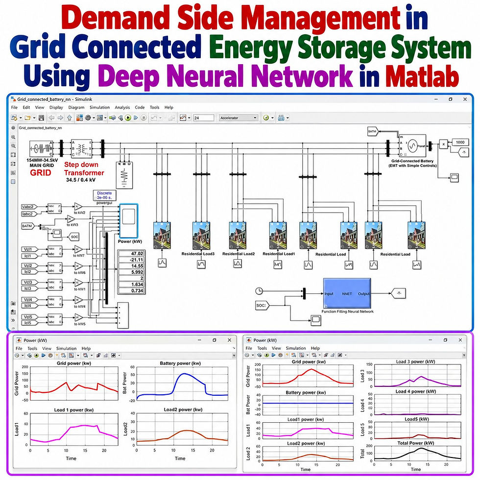
The model combines:
Utility grid
Step-down transformer
Multiple residential and commercial loads
Grid-connected battery energy storage
Battery charging and discharging control
Grid-side inverter control
Time-based load profiles
State of Charge (SOC) monitoring
Neural-network-based battery power reference generation
The main objective is to use the battery energy storage system to 𝐫𝐞𝐝𝐮𝐜𝐞 𝐩𝐞𝐚𝐤 𝐠𝐫𝐢𝐝 𝐩𝐨𝐰𝐞𝐫 while charging the battery during lower-demand periods.
𝐒𝐲𝐬𝐭𝐞𝐦 𝐎𝐯𝐞𝐫𝐯𝐢𝐞𝐰
The developed system represents a distribution network supplied from a high-power utility grid.
Main System Parameters
Parameter | Value / Description |
Main Grid Rating | 154 MW |
Grid Voltage | 34.5 kV |
Distribution Voltage | 400 V |
Transformer | 34.5 kV / 0.4 kV |
Simulation Period | 24 hours |
Load Data Interval | 30 minutes |
Number of Load Groups | 5 |
Neural Network Inputs | Time of Day + Battery SOC |
Neural Network Output | Battery Power Command |
Training Samples | 10,000 |
Hidden Neurons | 10 |
The transformer steps the grid voltage down from 34.5 kV to 400 V, allowing the distribution loads and grid-connected battery system to operate at the low-voltage level.
𝐋𝐨𝐚𝐝 𝐏𝐫𝐨𝐟𝐢𝐥𝐞 𝐂𝐨𝐧𝐟𝐢𝐠𝐮𝐫𝐚𝐭𝐢𝐨𝐧
The model contains different categories of loads representing practical variations in consumer demand throughout the day.
Load Group | Load Type |
Load 1 | Residential + Commercial |
Load 2 | Residential + Commercial |
Load 3 | Residential + Commercial |
Load 4 | Resistive Load |
Load 5 | Residential Load |
The load data is organized for a complete 24-hour period.
Load profile characteristics
Residential demand varies according to time of day.
Commercial demand also follows a predefined daily profile.
Load values are available at 30-minute intervals.
MATLAB/Simulink uses the stored data to generate dynamic load variations.
Each individual load contributes to the total system demand.
The total load is supplied jointly by the grid and battery energy storage system when DSM control is enabled.
This approach makes it possible to study how energy storage can support changing demand conditions.
𝐏𝐞𝐚𝐤 𝐚𝐧𝐝 𝐎𝐟𝐟-𝐏𝐞𝐚𝐤 𝐏𝐞𝐫𝐢𝐨𝐝𝐬
The 24-hour operating period is divided into peak and off-peak regions.
Time Period | Operating Region | Battery Objective |
0–10 h | Off-Peak | Charging support |
10–18 h | Peak | Discharge / grid support |
18–24 h | Off-Peak | Charging support |
During the 𝐩𝐞𝐚𝐤 𝐩𝐞𝐫𝐢𝐨𝐝, demand increases significantly. Without energy storage assistance, the utility grid must supply almost the entire load.
During 𝐨𝐟𝐟-𝐩𝐞𝐚𝐤 𝐩𝐞𝐫𝐢𝐨𝐝𝐬, the available grid capacity can be used to recharge the battery.
𝐆𝐫𝐢𝐝-𝐂𝐨𝐧𝐧𝐞𝐜𝐭𝐞𝐝 𝐁𝐚𝐭𝐭𝐞𝐫𝐲 𝐒𝐲𝐬𝐭𝐞𝐦
The energy storage subsystem consists of:
Battery
DC-link stage
Grid-connected inverter
Battery controller
Inverter controller
Power-reference input
SOC measurement
The inverter controller is responsible for maintaining proper operation with the AC grid, while the battery controller manages the required charging and discharging operation.
The battery becomes an active power-management element rather than simply remaining as backup storage.
𝐃𝐞𝐞𝐩 𝐍𝐞𝐮𝐫𝐚𝐥 𝐍𝐞𝐭𝐰𝐨𝐫𝐤 𝐂𝐨𝐧𝐭𝐫𝐨𝐥
The neural network generates the power command for the grid-connected battery.
Neural Network Inputs
The network receives two important operating variables:
𝐓𝐢𝐦𝐞 𝐨𝐟 𝐃𝐚𝐲
𝐁𝐚𝐭𝐭𝐞𝐫𝐲 𝐒𝐎𝐂
Neural Network Output
The network provides:
𝐁𝐚𝐭𝐭𝐞𝐫𝐲 𝐏𝐨𝐰𝐞𝐫 𝐂𝐨𝐦𝐦𝐚𝐧𝐝
The generated command determines whether the battery should:
Charge from the grid
Discharge into the grid-connected system
Reduce its contribution based on SOC
Remain within the predefined energy-management strategy
This allows the battery operation to change according to both the daily load period and the available stored energy.
𝐁𝐚𝐭𝐭𝐞𝐫𝐲 𝐏𝐨𝐰𝐞𝐫 𝐒𝐢𝐠𝐧 𝐂𝐨𝐧𝐯𝐞𝐧𝐭𝐢𝐨𝐧
The control description uses the following convention:
Battery Command | Battery Operating Mode |
Positive | Battery supplies power / discharging |
Negative | Battery absorbs power / charging |
Therefore:
𝐏𝐨𝐬𝐢𝐭𝐢𝐯𝐞 𝐩𝐨𝐰𝐞𝐫 supports the grid and loads.
𝐍𝐞𝐠𝐚𝐭𝐢𝐯𝐞 𝐩𝐨𝐰𝐞𝐫 represents battery charging.
The actual plotted signal should always be checked against the sign convention implemented inside the Simulink battery subsystem.
𝐖𝐨𝐫𝐤𝐢𝐧𝐠 𝐏𝐫𝐨𝐜𝐞𝐬𝐬
The DSM operation can be understood in a few stages.
1. Load Profile Generation
Residential and commercial load data are loaded into MATLAB/Simulink.
The individual loads vary over the simulated 24-hour period.
2. Total Demand Calculation
The different load groups combine to produce the overall demand profile.
Without battery support:
Grid power closely follows total load power.
Battery power remains approximately zero.
3. Identification of Operating Period
The controller identifies whether the present time belongs to:
Off-peak period
Peak period
4. Battery SOC Verification
Battery SOC is checked before selecting charging or discharging operation.
5. Neural Network Prediction
The trained network processes:
Time + SOC → Battery Power Reference
6. Battery Power Control
The predicted reference is passed to the grid-connected battery controller.
7. Peak Demand Reduction
During high-demand periods, stored battery energy supports the load and reduces the power requested from the utility grid.
8. Off-Peak Charging
During lower-demand periods, the battery is recharged from the grid according to the SOC condition.
𝐂𝐨𝐧𝐭𝐫𝐨𝐥 𝐒𝐭𝐫𝐚𝐭𝐞𝐠𝐲
The neural-network training data are generated using predefined DSM operating conditions.
Operating Logic
Time | SOC Condition | Intended Battery Action |
0–10 h | SOC below threshold | Charge |
10–12 h | SOC above threshold | Discharge with increasing support |
12–18 h | SOC above threshold | Discharge with gradually changing support |
18–24 h | SOC below threshold | Charge |
A commonly used SOC decision point in the demonstrated training logic is 50%.
The SOC condition prevents inappropriate battery operation when the stored energy level is insufficient or when additional charging is required.
𝐍𝐞𝐮𝐫𝐚𝐥 𝐍𝐞𝐭𝐰𝐨𝐫𝐤 𝐃𝐚𝐭𝐚 𝐆𝐞𝐧𝐞𝐫𝐚𝐭𝐢𝐨𝐧
To train the network, a large input-output dataset is first generated in MATLAB.
Training Dataset
Dataset Variable | Description |
Input 1 | Time of day |
Input 2 | Battery SOC |
Output | Battery power command |
Number of Samples | 10,000 |
The time and SOC values are generated across their operating ranges.
The desired battery command is then assigned according to:
Peak/off-peak period
Battery SOC
Required charging operation
Required discharge support
This produces the target dataset required for neural-network training.
𝐍𝐞𝐮𝐫𝐚𝐥 𝐍𝐞𝐭𝐰𝐨𝐫𝐤 𝐓𝐫𝐚𝐢𝐧𝐢𝐧𝐠
The generated input and target data are imported into the MATLAB neural-network training environment.
Training Procedure
Select the generated input matrix.
Select the corresponding target output.
Configure the input and target orientation correctly.
Divide the available samples for network development and evaluation.
Use 10 hidden neurons.
Select the required training algorithm.
Train the neural network.
Evaluate regression performance.
Deploy the trained network into Simulink.
The demonstrated workflow considers available training options such as:
Levenberg-Marquardt
Bayesian Regularization
Scaled Conjugate Gradient
The demonstrated training process selects the second option, Bayesian Regularization.
𝐑𝐞𝐠𝐫𝐞𝐬𝐬𝐢𝐨𝐧 𝐏𝐞𝐫𝐟𝐨𝐫𝐦𝐚𝐧𝐜𝐞
After training, the regression plot is used to check how closely the neural-network outputs match the target data.
The regression coefficient R should ideally be close to 1.
A value approaching 1 indicates a strong relationship between:
Target battery power commands
Neural-network predicted commands
The training, testing, and overall regression plots therefore provide a useful indication of network fitting quality.
𝐒𝐢𝐦𝐮𝐥𝐢𝐧𝐤 𝐃𝐞𝐩𝐥𝐨𝐲𝐦𝐞𝐧𝐭
After successful training, the trained neural network is converted into a Simulink-compatible block.
The deployed network receives:
Time of day
Battery SOC
and produces:
Battery power reference
This output is directly connected to the grid-connected battery control system.
As a result, the battery can automatically change its operating mode according to system requirements.
𝐂𝐚𝐬𝐞 𝟏: 𝐒𝐲𝐬𝐭𝐞𝐦 𝐖𝐢𝐭𝐡𝐨𝐮𝐭 𝐄𝐧𝐞𝐫𝐠𝐲 𝐒𝐭𝐨𝐫𝐚𝐠𝐞 𝐒𝐮𝐩𝐩𝐨𝐫𝐭
The first simulation evaluates system performance when the battery does not participate in power sharing.
Observations
Battery power remains near zero.
Grid supplies practically the complete load demand.
Grid power closely follows total load power.
Demand becomes high during the peak period.
Peak grid power reaches approximately 160 kW in the demonstrated profile.
This provides a baseline for evaluating the effect of DSM.
𝐂𝐚𝐬𝐞 𝟐: 𝐃𝐒𝐌 𝐖𝐢𝐭𝐡 𝐍𝐞𝐮𝐫𝐚𝐥 𝐍𝐞𝐭𝐰𝐨𝐫𝐤 𝐚𝐧𝐝 𝐁𝐚𝐭𝐭𝐞𝐫𝐲
In the second case, the trained network controls the battery power reference.
During Off-Peak Hours
The controller can command battery charging when:
Demand is relatively low.
Battery SOC requires charging.
Additional stored energy will be useful for the next peak-demand period.
During Peak Hours
The battery supplies part of the required demand when sufficient stored energy is available.
Therefore:
Grid power demand is reduced.
The peak portion of the grid power curve is clipped.
Load demand continues to be supplied.
Stored battery energy is utilized strategically.
𝐒𝐢𝐦𝐮𝐥𝐚𝐭𝐢𝐨𝐧 𝐑𝐞𝐬𝐮𝐥𝐭𝐬
The MATLAB/Simulink results demonstrate the difference between normal grid operation and neural-network-based DSM.
Performance Aspect | Without DSM | With DNN-Based DSM |
Grid supplies total demand | Yes | Partially |
Battery participation | No | Yes |
Off-peak battery charging | No | Yes |
Peak-period battery support | No | Yes |
Peak power reduction | No | Achieved |
SOC-based decision making | No | Yes |
Intelligent power command | No | Neural network |
Load demand supplied | Yes | Yes |
Major Result
Without battery support, the grid power rises to approximately 160 kW for the demonstrated high-demand portion of the profile.
After introducing the neural-network-controlled battery:
The high-power section of the grid demand is reduced.
Battery power compensates for part of the peak load.
The resulting grid profile becomes smoother.
Battery energy is restored during suitable off-peak periods.
This demonstrates the basic concept of 𝐩𝐞𝐚𝐤 𝐜𝐥𝐢𝐩𝐩𝐢𝐧𝐠 𝐮𝐬𝐢𝐧𝐠 𝐞𝐧𝐞𝐫𝐠𝐲 𝐬𝐭𝐨𝐫𝐚𝐠𝐞.
𝐁𝐞𝐟𝐨𝐫𝐞 𝐚𝐧𝐝 𝐀𝐟𝐭𝐞𝐫 𝐃𝐒𝐌 𝐂𝐨𝐦𝐩𝐚𝐫𝐢𝐬𝐨𝐧
Normal Grid Operation
Grid directly follows load demand.
Battery does not contribute power.
Peak grid demand remains high.
No intelligent power scheduling is performed.
Neural-Network-Based DSM
Battery charging is scheduled during suitable off-peak intervals.
Battery energy is used during peak periods.
SOC is considered before battery power is commanded.
Peak grid power is clipped.
Power sharing between grid and battery becomes dynamic.
𝐖𝐡𝐲 𝐔𝐬𝐞 𝐚 𝐃𝐞𝐞𝐩 𝐍𝐞𝐮𝐫𝐚𝐥 𝐍𝐞𝐭𝐰𝐨𝐫𝐤?
Traditional control can be implemented using several fixed decision rules. A neural network provides a convenient way to learn the required battery command from generated operating data.
The trained network can map:
Time of Day + SOC → Required Battery Power
This makes the control structure suitable for intelligent energy-management studies involving multiple operating conditions.
𝐊𝐞𝐲 𝐅𝐞𝐚𝐭𝐮𝐫𝐞𝐬
154 MW, 34.5 kV utility grid
34.5 kV/400 V distribution transformer
24-hour load simulation
30-minute load-profile data
Residential and commercial load variation
Five load groups
Grid-connected battery energy storage
Battery SOC monitoring
Peak and off-peak classification
10,000 neural-network training samples
Time and SOC as network inputs
Battery power reference as network output
10 hidden neurons
Neural-network regression analysis
Simulink deployment of trained network
Battery charging and discharging management
Peak-demand clipping
Grid power reduction during high-demand periods
𝐀𝐩𝐩𝐥𝐢𝐜𝐚𝐭𝐢𝐨𝐧𝐬
This type of DSM architecture can be useful for studying:
Smart grid energy management
Battery energy storage systems
Residential energy management
Commercial load scheduling
Distribution network peak shaving
Microgrid energy management
Smart building energy control
Utility demand response
Intelligent battery scheduling
Artificial-intelligence-based power management
Grid-support energy storage
Peak-load reduction strategies
𝐁𝐞𝐧𝐞𝐟𝐢𝐭𝐬 𝐨𝐟 𝐃𝐞𝐦𝐚𝐧𝐝 𝐒𝐢𝐝𝐞 𝐌𝐚𝐧𝐚𝐠𝐞𝐦𝐞𝐧𝐭
The proposed simulation concept highlights several potential benefits:
Reduces peak power drawn from the utility grid.
Utilizes stored battery energy during high-demand periods.
Charges energy storage during lower-demand periods.
Improves utilization of the battery system.
Supports smoother grid power flow.
Coordinates load demand and stored energy.
Uses SOC information for safer power scheduling.
Demonstrates intelligent battery power management using machine learning.
𝐂𝐨𝐧𝐜𝐥𝐮𝐬𝐢𝐨𝐧
The Demand Side Management in Grid Connected Energy Storage System Using Deep Neural Network model demonstrates how battery storage can be intelligently coordinated with time-varying residential and commercial loads.
The developed MATLAB/Simulink system considers a 154 MW, 34.5 kV grid, a 34.5 kV/400 V transformer, multiple dynamic loads, a grid-connected battery, SOC monitoring, and neural-network-based battery power control.
A dataset containing 10,000 operating samples is used to train the network using time of day and battery SOC as inputs. The resulting battery power command is then deployed within Simulink.
Simulation results illustrate that energy storage can charge during suitable off-peak periods and contribute power during peak-demand periods. Compared with the system without battery support, the neural-network-controlled DSM strategy reduces the high-demand portion of grid power while maintaining the required load supply.
This model provides a clear MATLAB/Simulink framework for understanding 𝐬𝐦𝐚𝐫𝐭 𝐠𝐫𝐢𝐝 𝐃𝐒𝐌, 𝐛𝐚𝐭𝐭𝐞𝐫𝐲 𝐞𝐧𝐞𝐫𝐠𝐲 𝐬𝐭𝐨𝐫𝐚𝐠𝐞, 𝐩𝐞𝐚𝐤 𝐬𝐡𝐚𝐯𝐢𝐧𝐠, 𝐚𝐧𝐝 𝐧𝐞𝐮𝐫𝐚𝐥-𝐧𝐞𝐭𝐰𝐨𝐫𝐤-𝐛𝐚𝐬𝐞𝐝 𝐞𝐧𝐞𝐫𝐠𝐲 𝐦𝐚𝐧𝐚𝐠𝐞𝐦𝐞𝐧𝐭.


Comments