


DC Microgrid PV System with Battery Energy System

DC Microgrid PV System with Battery Energy System
𝐈𝐧𝐭𝐫𝐨𝐝𝐮𝐜𝐭𝐢𝐨𝐧
DC microgrids are increasingly used in renewable-energy-based electrical systems because many modern energy sources and loads naturally operate with DC power.
DC Microgrid PV System with Battery Energy System
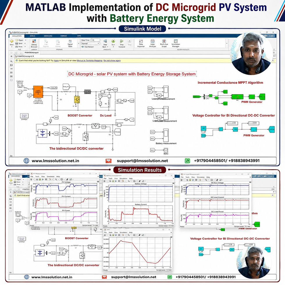
In this MATLAB/Simulink model:
Solar PV acts as the primary renewable energy source.
A battery provides energy storage and power balancing.
A boost converter interfaces the PV array with the DC bus.
A bidirectional DC–DC converter connects the battery.
Incremental Conductance MPPT extracts maximum PV power.
A voltage controller regulates the DC-link voltage.
A DC load demonstrates system power-sharing performance.
The system is tested under rapidly changing solar irradiation to verify the response of the PV array, battery, converters, and DC bus.
𝐒𝐲𝐬𝐭𝐞𝐦 𝐎𝐯𝐞𝐫𝐯𝐢𝐞𝐰
The simulated DC microgrid contains the following main sections:
Solar PV array
Incremental Conductance MPPT
DC–DC boost converter
400 V DC bus
DC load
Battery energy storage system
Bidirectional DC–DC converter
PI-based DC bus voltage controller
PWM pulse generation
Voltage, current, power, and SOC measurement
Main System Architecture
Solar PV Array → Boost Converter → 400 V DC Bus → DC Load
The battery is connected to the common DC bus through a bidirectional DC–DC converter, allowing energy transfer in both charging and discharging directions.
𝐒𝐨𝐥𝐚𝐫 𝐏𝐕 𝐒𝐲𝐬𝐭𝐞𝐦 𝐏𝐚𝐫𝐚𝐦𝐞𝐭𝐞𝐫𝐬
The PV array is developed using 250 W photovoltaic modules.
Parameter | Value |
Single PV module rated power | 250 W |
Open-circuit voltage | 37.3 V |
Short-circuit current | 8.6 A |
Voltage at maximum power point | 30.7 V |
Current at maximum power point | 8.15 A |
Series-connected modules | 8 |
Parallel strings | 1 |
Approximate PV array rated power | 2 kW |
Approximate PV MPP voltage | 245.6 V |
Regulated DC bus voltage | 400 V |
With eight modules connected in series, the PV array operates at approximately 245 V near the maximum power point under standard operating conditions.
The boost converter increases this PV-side voltage to the required 400 V DC bus level.
𝐏𝐕 𝐂𝐡𝐚𝐫𝐚𝐜𝐭𝐞𝐫𝐢𝐬𝐭𝐢𝐜𝐬
The PV output changes according to solar irradiation.
At high irradiation, both PV current and available PV power increase. When irradiation decreases, the available current and output power decrease significantly.
Typical PV power levels are approximately:
Solar Irradiation | Approximate PV Power |
1000 W/m² | 2000 W |
800 W/m² | 1600 W |
600 W/m² | 1200 W |
400 W/m² | 800 W |
These characteristics show why an MPPT controller is important. Without MPPT, the PV array may not operate continuously near its maximum available power point.
𝐈𝐧𝐜𝐫𝐞𝐦𝐞𝐧𝐭𝐚𝐥 𝐂𝐨𝐧𝐝𝐮𝐜𝐭𝐚𝐧𝐜𝐞 𝐌𝐏𝐏𝐓
The model uses the Incremental Conductance Maximum Power Point Tracking algorithm to control the PV boost converter.
The controller receives:
PV voltage
PV current
From these measurements, it continuously determines the required duty cycle for the boost converter.
MPPT Initialization
The controller initially defines parameters such as:
Initial duty cycle
Maximum duty cycle
Minimum duty cycle
Duty-cycle increment
Previous PV voltage
Previous PV current
Previous PV power
Previous duty cycle
These stored previous values are used to identify the direction in which the PV operating point should be shifted.
𝐌𝐏𝐏𝐓 𝐖𝐨𝐫𝐤𝐢𝐧𝐠 𝐏𝐫𝐨𝐜𝐞𝐬𝐬
The Incremental Conductance controller operates in the following sequence:
Measure the PV voltage and PV current.
Determine the present PV power.
Compare current measurements with previous measurements.
Identify whether the PV operating point is:
Below the maximum power point
At the maximum power point
Above the maximum power point
Increase or decrease the converter duty cycle accordingly.
Check the duty cycle against its allowable upper and lower limits.
Update the previous voltage, current, power, and duty-cycle values.
Repeat the process continuously during simulation.
When the PV array reaches the maximum power region, the controller keeps the duty cycle nearly unchanged.
𝐁𝐨𝐨𝐬𝐭 𝐂𝐨𝐧𝐯𝐞𝐫𝐭𝐞𝐫 𝐂𝐨𝐧𝐭𝐫𝐨𝐥
The duty cycle generated by the Incremental Conductance algorithm is sent to the PWM generator.
The PWM generator produces switching pulses for the boost converter.
The boost converter performs two important functions:
Extracts maximum available energy from the PV array.
Raises the PV operating voltage from approximately 245 V to the 400 V DC bus.
Therefore, the MPPT algorithm and boost converter operate together as the PV-side energy conversion stage.
𝐁𝐚𝐭𝐭𝐞𝐫𝐲 𝐄𝐧𝐞𝐫𝐠𝐲 𝐒𝐭𝐨𝐫𝐚𝐠𝐞 𝐒𝐲𝐬𝐭𝐞𝐦
A battery is connected to the DC microgrid to maintain reliable power delivery when PV generation changes.
Battery Parameter | Value |
Nominal battery voltage | Approximately 240 V |
Battery capacity | Approximately 40 Ah |
Connection | Bidirectional DC–DC converter |
Main operating modes | Charging and discharging |
The battery does not remain permanently in one operating state. Its charging or discharging condition depends on the relationship between:
Available PV power
DC load requirement
Converter and system losses
𝐁𝐢𝐝𝐢𝐫𝐞𝐜𝐭𝐢𝐨𝐧𝐚𝐥 𝐃𝐂–𝐃𝐂 𝐂𝐨𝐧𝐯𝐞𝐫𝐭𝐞𝐫
The battery is interfaced with the DC bus through a bidirectional converter.
Unlike a conventional unidirectional converter, this converter allows power flow in both directions.
Battery Charging
When solar PV generation is higher than the DC load requirement:
The load receives the required power.
Excess PV energy is transferred to the battery.
Battery current becomes negative according to the sign convention used in the simulation.
Battery SOC gradually increases.
Battery Discharging
When PV generation is lower than load demand:
The battery supplies the missing power.
Battery current becomes positive.
Battery SOC decreases.
The DC load continues receiving the required power.
This automatic transition provides effective power balancing in the DC microgrid.
𝐂𝐨𝐧𝐭𝐫𝐨𝐥 𝐒𝐭𝐫𝐚𝐭𝐞𝐠𝐲
Two major control systems are implemented.
1. PV-Side Control
The PV-side controller contains:
PV voltage measurement
PV current measurement
Incremental Conductance MPPT
Duty-cycle generation
PWM generator
Boost converter
Its main objective is maximum solar power extraction.
2. Battery-Side Control
The battery-side controller contains:
DC bus voltage measurement
400 V voltage reference
Voltage error generation
PI controller
PWM generation
Bidirectional converter
Its main objective is DC bus voltage regulation and battery power management.
𝐃𝐂 𝐁𝐮𝐬 𝐕𝐨𝐥𝐭𝐚𝐠𝐞 𝐂𝐨𝐧𝐭𝐫𝐨𝐥
The reference DC bus voltage is fixed at:
400 V
The actual DC bus voltage is continuously measured and compared with this reference.
Any voltage deviation is processed by a PI controller.
The resulting control signal determines the duty cycle of the battery converter.
This enables the battery converter to compensate for sudden variations in PV generation and helps keep the DC bus close to 400 V.
𝐃𝐂 𝐋𝐨𝐚𝐝
The simulated load requires approximately:
Load Parameter | Value |
DC bus voltage | 400 V |
DC load current | Approximately 2.5 A |
DC load power | Approximately 1000 W |
The load requirement remains approximately constant while PV irradiation is varied.
This makes it possible to clearly observe how the battery compensates for changing PV generation.
𝐒𝐢𝐦𝐮𝐥𝐚𝐭𝐢𝐨𝐧 𝐈𝐫𝐫𝐚𝐝𝐢𝐚𝐧𝐜𝐞 𝐏𝐫𝐨𝐟𝐢𝐥𝐞
To evaluate dynamic operation, the solar irradiation is changed every 0.3 seconds.
Time Range | Irradiation |
Initial interval | 1000 W/m² |
Next interval | 500 W/m² |
Next interval | 10 W/m² |
Next interval | 500 W/m² |
Final interval | 1000 W/m² |
This profile creates high-generation, reduced-generation, nearly zero-generation, recovery, and full-generation conditions.
𝐒𝐢𝐦𝐮𝐥𝐚𝐭𝐢𝐨𝐧 𝐑𝐞𝐬𝐮𝐥𝐭𝐬
The simulation demonstrates stable operation under large solar irradiation changes.
PV Performance at 1000 W/m²
At approximately 1000 W/m²:
PV power is close to 2000 W.
PV voltage remains around 245 V.
PV current is approximately 8 A.
The DC load requires only around 1000 W.
The remaining solar energy is available for battery charging.
The battery current becomes negative, indicating the charging condition.
PV Performance at 500 W/m²
At approximately 500 W/m²:
PV power decreases to around 1000 W.
PV voltage remains near the MPP operating region.
PV current decreases to approximately 4 A.
PV generation becomes close to the load requirement.
The battery may provide a small amount of supporting current to compensate for converter and system losses.
PV Performance at 10 W/m²
When irradiation is reduced to approximately 10 W/m²:
PV current approaches zero.
PV output power becomes almost zero.
The PV array cannot support the load.
The battery immediately changes to discharging operation.
Battery current becomes positive.
The battery supplies the DC load.
Battery SOC decreases more rapidly.
This condition clearly demonstrates the importance of energy storage in maintaining uninterrupted DC microgrid operation.
Recovery to 500 W/m²
When irradiation returns to 500 W/m²:
PV generation recovers to approximately 1000 W.
Battery discharge requirement decreases.
Power sharing returns close to the balanced condition.
The DC bus remains regulated.
Recovery to 1000 W/m²
When irradiation returns to 1000 W/m²:
PV power increases to approximately 2000 W.
The load continues consuming approximately 1000 W.
Surplus solar power is directed toward the battery.
Battery current becomes negative.
Battery SOC begins increasing again.
𝐑𝐞𝐬𝐮𝐥𝐭 𝐒𝐮𝐦𝐦𝐚𝐫𝐲
Operating Condition | PV Power | Battery Condition | DC Load | DC Bus |
1000 W/m² | ≈2000 W | Charging | ≈1000 W | ≈400 V |
500 W/m² | ≈1000 W | Small support / near balance | ≈1000 W | ≈400 V |
10 W/m² | Nearly 0 W | Discharging | ≈1000 W | ≈400 V |
500 W/m² recovery | ≈1000 W | Small support / near balance | ≈1000 W | ≈400 V |
1000 W/m² recovery | ≈2000 W | Charging | ≈1000 W | ≈400 V |
𝐁𝐚𝐭𝐭𝐞𝐫𝐲 𝐒𝐎𝐂 𝐁𝐞𝐡𝐚𝐯𝐢𝐨𝐫
The battery State of Charge confirms the direction of power flow.
During Charging
Battery current is negative.
Excess solar energy enters the battery.
SOC gradually increases.
During Discharging
Battery current is positive.
The battery supplies the DC load.
SOC decreases.
The strongest SOC decrease occurs when PV irradiation is reduced to approximately 10 W/m², because almost the entire load requirement must be supplied by the battery.
𝐏𝐨𝐰𝐞𝐫 𝐒𝐡𝐚𝐫𝐢𝐧𝐠 𝐁𝐞𝐡𝐚𝐯𝐢𝐨𝐫
The system automatically adjusts power sharing without requiring a fixed time-based charging or discharging command.
High PV Generation
PV → DC Load + Battery Charging
PV Generation Near Load Demand
PV → DC Load, with the battery providing only the small additional power required to compensate for system losses.
Very Low PV Generation
Battery → DC Bus → DC Load
This makes the system responsive to the actual renewable generation and load condition.
𝐊𝐞𝐲 𝐅𝐞𝐚𝐭𝐮𝐫𝐞𝐬
MATLAB/Simulink implementation of a complete DC microgrid
2 kW-class solar PV array
Incremental Conductance MPPT
Automatic maximum power extraction
PV-side boost converter
Approximately 245 V PV operating voltage
Regulated 400 V DC bus
Battery energy storage integration
Bidirectional DC–DC converter
Automatic battery charging and discharging
PI-based DC voltage control
PWM converter control
Dynamic solar irradiation testing
PV voltage, current, and power monitoring
Battery voltage and current monitoring
Battery SOC analysis
DC load voltage, current, and power measurement
Continuous renewable-energy power balancing
𝐀𝐝𝐯𝐚𝐧𝐭𝐚𝐠𝐞𝐬
The proposed configuration provides several advantages:
Better utilization of available solar energy
Reliable DC load supply during low irradiation
Automatic storage of excess renewable energy
Reduced DC bus voltage fluctuation
Smooth transition between charging and discharging
Effective use of battery energy storage
Simple and understandable control architecture
Suitable platform for studying DC microgrid energy management
Easy observation of renewable-generation and storage interactions
𝐀𝐩𝐩𝐥𝐢𝐜𝐚𝐭𝐢𝐨𝐧𝐬
This type of DC microgrid architecture can be studied for applications such as:
Solar-powered DC distribution systems
Battery-supported renewable energy systems
DC buildings
Telecom DC power systems
Data-center DC distribution
Renewable-powered charging infrastructure
Residential DC energy systems
Industrial DC networks
Remote renewable energy systems
Energy storage control studies
Microgrid controller development
MPPT algorithm evaluation
𝐖𝐡𝐲 𝐔𝐬𝐞 𝐁𝐚𝐭𝐭𝐞𝐫𝐲 𝐒𝐭𝐨𝐫𝐚𝐠𝐞 𝐢𝐧 𝐚 𝐃𝐂 𝐌𝐢𝐜𝐫𝐨𝐠𝐫𝐢𝐝?
Solar energy is naturally intermittent. Cloud movement and changes in irradiation can cause PV generation to change quickly.
The battery solves this problem by acting as an energy buffer.
When PV generation is high, it stores surplus energy. When PV generation falls below load demand, it releases stored energy.
As demonstrated in this simulation, even when the PV output becomes almost zero, the battery continues supporting the approximately 1 kW DC load while the DC bus remains close to 400 V.
𝐖𝐡𝐲 𝐔𝐬𝐞 𝐈𝐧𝐜𝐫𝐞𝐦𝐞𝐧𝐭𝐚𝐥 𝐂𝐨𝐧𝐝𝐮𝐜𝐭𝐚𝐧𝐜𝐞 𝐌𝐏𝐏𝐓?
Incremental Conductance MPPT is useful when solar irradiation changes because the controller continuously checks changes in PV voltage and current.
Its advantages include:
Continuous tracking of the PV maximum power region
Good response to irradiation variations
Reduced unnecessary movement around the maximum power point
Direct control of the PV boost converter duty cycle
Suitability for MATLAB/Simulink implementation
In this model, the MPPT successfully tracks the available PV power as irradiation changes from 1000 W/m² down to 10 W/m² and back to 1000 W/m².
𝐖𝐡𝐲 𝐔𝐬𝐞 𝐚 𝐁𝐢𝐝𝐢𝐫𝐞𝐜𝐭𝐢𝐨𝐧𝐚𝐥 𝐂𝐨𝐧𝐯𝐞𝐫𝐭𝐞𝐫?
A battery needs two-way energy transfer.
A bidirectional converter allows:
DC bus to battery energy transfer during charging.
Battery to DC bus energy transfer during discharging.
The same converter also participates in DC bus voltage regulation, making it an essential part of the battery energy storage system.
𝐂𝐨𝐧𝐜𝐥𝐮𝐬𝐢𝐨𝐧
The DC Microgrid PV System with Battery Energy System in MATLAB/Simulink demonstrates effective coordination between renewable generation, battery storage, DC–DC converters, and load demand.
The Incremental Conductance MPPT enables the PV array to track the available maximum power under changing irradiation. The PV boost converter raises the approximately 245 V PV-side voltage to a 400 V DC bus, while the battery-side bidirectional converter maintains DC bus stability.
Simulation results show that the PV array produces approximately 2 kW at 1000 W/m², around 1 kW at 500 W/m², and almost zero power at 10 W/m². When surplus PV power is available, the battery charges. When solar generation becomes insufficient, the battery automatically discharges and supports the approximately 1 kW DC load.
Overall, the model provides a clear platform for understanding DC microgrid operation, solar MPPT control, battery energy management, bidirectional power flow, and DC bus voltage regulation.


Comments