


𝐀𝐍𝐍 𝐁𝐚𝐬𝐞𝐝 𝐌𝐏𝐏𝐓 𝐟𝐨𝐫 𝐒𝐨𝐥𝐚𝐫 𝐏𝐕 𝐁𝐚𝐭𝐭𝐞𝐫𝐲 𝐏𝐨𝐰𝐞𝐫𝐞𝐝 𝐁𝐋𝐃𝐂 𝐌𝐨𝐭𝐨𝐫

𝐀𝐍𝐍 𝐁𝐚𝐬𝐞𝐝 𝐌𝐏𝐏𝐓 𝐟𝐨𝐫 𝐒𝐨𝐥𝐚𝐫 𝐏𝐕 𝐁𝐚𝐭𝐭𝐞𝐫𝐲 𝐏𝐨𝐰𝐞𝐫𝐞𝐝 𝐁𝐋𝐃𝐂 𝐌𝐨𝐭𝐨𝐫
𝐈𝐧𝐭𝐫𝐨𝐝𝐮𝐜𝐭𝐢𝐨𝐧
Solar-powered motor-drive systems offer a clean and efficient solution for applications requiring reliable electrical energy and controlled motor operation.
𝐀𝐍𝐍 𝐁𝐚𝐬𝐞𝐝 𝐌𝐏𝐏𝐓 𝐟𝐨𝐫 𝐒𝐨𝐥𝐚𝐫 𝐏𝐕 𝐁𝐚𝐭𝐭𝐞𝐫𝐲 𝐏𝐨𝐰𝐞𝐫𝐞𝐝 𝐁𝐋𝐃𝐂 𝐌𝐨𝐭𝐨𝐫
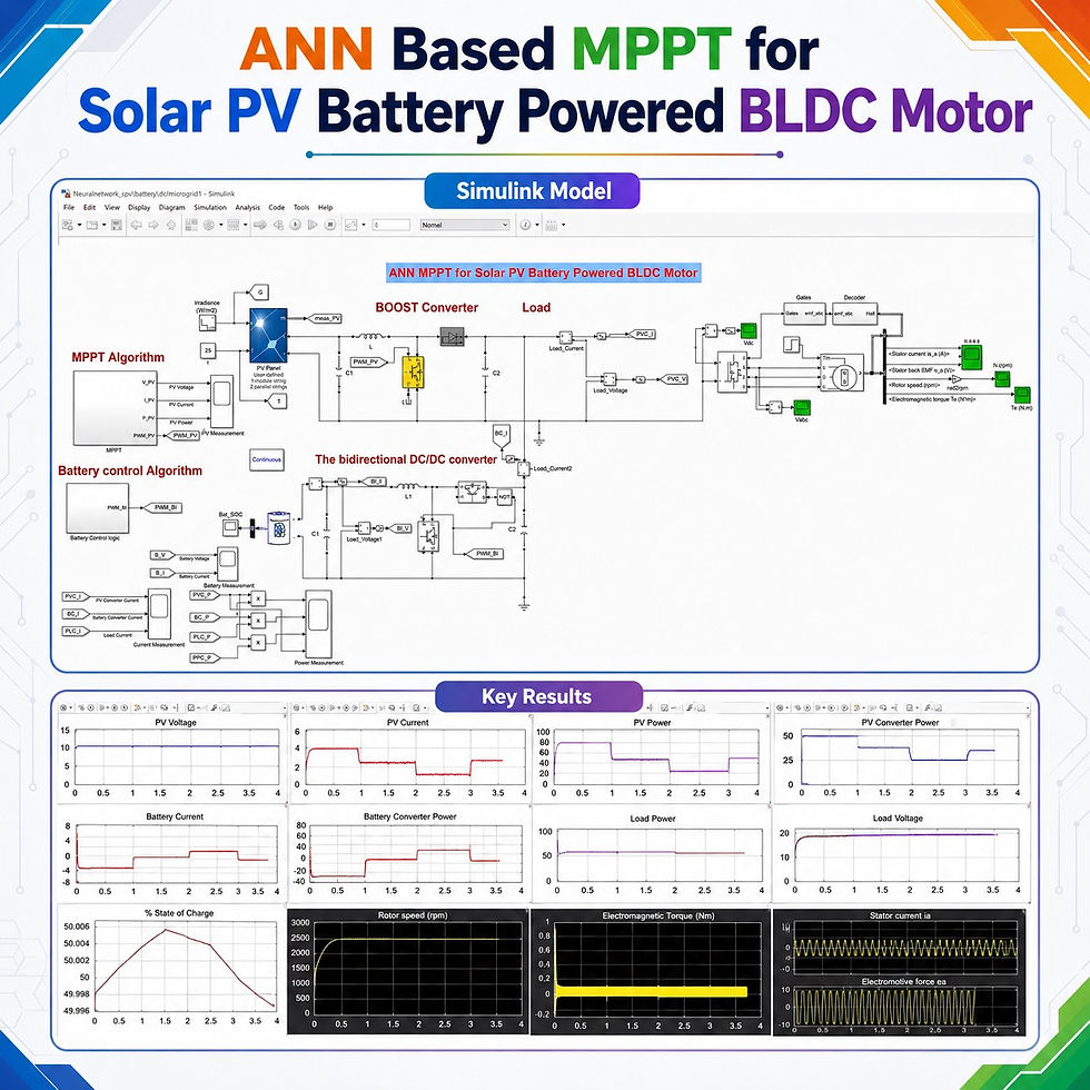
This MATLAB/Simulink model presents an ANN-based maximum power point tracking system for operating a 24 V BLDC motor using:
A solar PV array
An artificial neural network MPPT controller
A boost converter
A 12 V battery
A bidirectional DC–DC converter
A voltage-regulated DC link
A voltage-source inverter
A BLDC motor drive
The artificial neural network MPPT controller extracts maximum available power from the PV array under changing solar irradiance and temperature conditions.
The battery supports the motor when the available PV power decreases and absorbs surplus solar power when PV generation exceeds the motor requirement.
𝐒𝐲𝐬𝐭𝐞𝐦 𝐎𝐯𝐞𝐫𝐯𝐢𝐞𝐰
The system is designed around a 24 V DC bus and a small 24 V BLDC motor.
The complete power flow is:
Solar PV Array → Boost Converter → 24 V DC Bus → Inverter → BLDC Motor
The battery is connected to the DC bus through a bidirectional DC–DC converter.
Main system sections
Section | Main function |
Solar PV array | Generates electrical power from solar energy |
ANN MPPT controller | Determines the optimum PV operating voltage |
Boost converter | Raises the PV voltage to the required DC-bus level |
Battery storage | Stores surplus energy and supplies deficit power |
Bidirectional converter | Controls battery charging and discharging |
DC bus | Maintains the required 24 V supply |
Voltage-source inverter | Converts DC power into the required motor supply |
BLDC motor | Converts electrical energy into mechanical output |
Gate decoder | Produces inverter switching signals using rotor-position information |
𝐁𝐋𝐃𝐂 𝐌𝐨𝐭𝐨𝐫 𝐏𝐚𝐫𝐚𝐦𝐞𝐭𝐞𝐫𝐬
The motor is configured using standard manufacturer specifications. A trapezoidal back-EMF model is selected in the BLDC motor block.
Parameter | Value |
Rated voltage | 24 V |
Rated power | Approximately 39–40 W |
Rated speed | 3000 rpm |
Rated torque | 0.125 N·m |
Rated current | Approximately 2.5 A |
Peak current | 7.5 A |
Peak torque | 0.375 N·m |
Torque constant | 0.05 N·m/A |
Line-to-line resistance | 1.35 Ω |
Number of poles | 8 |
Number of pole pairs | 4 |
Moment of inertia | 0.33 kg·cm² |
Back-EMF type | Trapezoidal |
After computing the block parameters from the manufacturer data, the model reports:
Computed parameter | Value |
Stator phase resistance | 0.675 Ω |
Stator phase inductance | 0.0045 |
Computed voltage-related parameter | Approximately 0.236 |
These parameters are applied directly to the BLDC motor model in MATLAB/Simulink.
𝐒𝐨𝐥𝐚𝐫 𝐏𝐕 𝐀𝐫𝐫𝐚𝐲 𝐂𝐨𝐧𝐟𝐢𝐠𝐮𝐫𝐚𝐭𝐢𝐨𝐧
The PV array is selected with a power rating higher than the BLDC motor rating. This allows the PV system to operate the motor and charge the battery when sufficient solar energy is available.
PV parameter | Value |
Approximate single-panel power | 49 W |
Number of parallel panels | 2 |
Total PV power | Approximately 100 W |
Voltage at maximum power point | 17 V |
Current at maximum power point per panel | 2.941 A |
Approximate total PV current | 5.8 A |
Required DC-bus voltage | 24 V |
Connecting two panels in parallel maintains the PV voltage at approximately 17 V while increasing the available current and total power.
𝐁𝐚𝐭𝐭𝐞𝐫𝐲 𝐂𝐨𝐧𝐟𝐢𝐠𝐮𝐫𝐚𝐭𝐢𝐨𝐧
The battery provides energy storage and supports the BLDC motor during low solar-power conditions.
Battery parameter | Value |
Nominal voltage | 12 V |
Capacity | 100 Ah |
Converter power rating | Approximately 100 W |
DC-bus voltage | 24 V |
Initial state of charge | Approximately 50% |
Operating modes | Charging and discharging |
Because the battery voltage is lower than the DC-bus voltage, a bidirectional converter is used to control power exchange between the battery and the DC bus.
𝐖𝐨𝐫𝐤𝐢𝐧𝐠 𝐏𝐫𝐨𝐜𝐞𝐬𝐬
1. Solar-power generation
The PV array produces power according to the applied irradiance and temperature.
Higher irradiance produces more PV current and power.
Lower irradiance reduces the available solar power.
The PV voltage is controlled near its optimum operating point.
2. ANN-based maximum power point tracking
The neural network receives two main inputs:
Solar irradiance
PV temperature
The trained ANN produces the required reference PV voltage.
This reference voltage is compared with the measured PV voltage. The voltage error is then processed by a PI controller.
3. Boost-converter operation
The PI controller generates the required duty-cycle command.
The duty cycle is supplied to a PWM generator, which produces the switching pulse for the boost-converter IGBT.
The boost converter:
Raises the PV voltage from approximately 17 V
Supplies power to the 24 V DC bus
Maintains the PV array near its maximum-power operating point
4. DC-bus voltage regulation
The DC-bus voltage is measured and compared with the 24 V reference.
The voltage error is processed by a PI controller. Its output controls the PWM pulses of the bidirectional converter.
This control maintains the inverter input voltage close to 24 V even when solar irradiance changes.
5. BLDC motor operation
The regulated DC voltage is supplied to the inverter.
The inverter and gate-decoder system energize the BLDC motor phases according to the rotor-position signals.
The motor operates at the specified load torque while the model monitors:
Rotor speed
Electromagnetic torque
Stator current
Back EMF
Inverter input power
DC-link voltage
𝐂𝐨𝐧𝐭𝐫𝐨𝐥 𝐒𝐭𝐫𝐚𝐭𝐞𝐠𝐲
The system uses two major control loops.
ANN MPPT control
Control stage | Description |
Inputs | Solar irradiance and temperature |
ANN output | Reference PV voltage |
Feedback signal | Actual PV voltage |
Error controller | PI controller |
Modulation | PWM generator |
Controlled converter | PV boost converter |
Main objective | Maximum PV power extraction |
The ANN learns the relationship between environmental conditions and the optimum PV voltage.
Compared with a fixed operating point, the ANN controller can adjust the PV reference as irradiance and temperature change.
Battery-converter control
Control stage | Description |
Reference value | 24 V |
Feedback signal | Measured DC-bus voltage |
Error controller | PI controller |
Modulation | PWM generator |
Controlled converter | Bidirectional DC–DC converter |
Main objective | DC-bus voltage regulation |
Secondary function | Battery charging and discharging |
The bidirectional converter automatically changes the direction of battery power depending on the available PV power and motor demand.
𝐁𝐚𝐭𝐭𝐞𝐫𝐲 𝐏𝐨𝐰𝐞𝐫-𝐅𝐥𝐨𝐰 𝐋𝐨𝐠𝐢𝐜
The BLDC motor requires approximately 40 W at its rated operating point. The PV array can produce nearly 100 W under high irradiance.
When PV power is higher than the motor requirement
The PV array operates the BLDC motor.
Excess PV power is transferred to the battery.
Battery current becomes negative according to the model sign convention.
Battery-converter power becomes negative.
Battery state of charge increases.
When PV power is lower than the motor requirement
The PV array continues supplying available power.
The battery supplies the remaining required power.
Battery current becomes positive.
Battery-converter power becomes positive.
Battery state of charge decreases.
The DC-bus voltage remains close to 24 V.
Power-flow interpretation
Operating condition | Battery mode | Battery-current sign | Battery-power sign |
Surplus PV power | Charging | Negative | Negative |
Insufficient PV power | Discharging | Positive | Positive |
𝐒𝐢𝐦𝐮𝐥𝐚𝐭𝐢𝐨𝐧 𝐂𝐨𝐧𝐝𝐢𝐭𝐢𝐨𝐧𝐬
The model is tested under changing irradiance conditions.
Simulation parameter | Applied value |
Irradiance profile | 1000, 600, 400 and 600 W/m² |
Irradiance-changing interval | Approximately every 1 second |
Motor load torque | 0.125 N·m |
DC-bus reference | 24 V |
Initial battery state of charge | Approximately 50% |
Motor rated speed | 3000 rpm |
The results include measurements of:
PV voltage
PV current
PV power
PV-converter output power
Battery voltage
Battery current
Battery state of charge
Battery-converter power
Load power
DC-bus voltage
Rotor speed
Electromagnetic torque
Stator current
Back EMF
𝐒𝐢𝐦𝐮𝐥𝐚𝐭𝐢𝐨𝐧 𝐑𝐞𝐬𝐮𝐥𝐭𝐬
Operation at high irradiance
At approximately 1000 W/m²:
Observed quantity | Approximate result |
PV voltage | 17 V |
PV current | 5.8–5.9 A |
PV power | Approximately 95–100 W |
Battery current | Approximately −2 A |
Battery-converter power | Approximately −35 W |
Inverter input or load power | Approximately 60 W |
DC-bus voltage | Approximately 24 V |
Battery operating mode | Charging |
Battery SoC | Increases from approximately 50% |
The negative battery current indicates that surplus PV power is being stored in the battery.
The PV array supplies the motor load while the remaining power charges the battery.
Operation at reduced irradiance
When irradiance decreases from 1000 W/m² to approximately 600 W/m²:
Observed quantity | Approximate result |
PV power | Approximately 60 W |
Reduction in PV power | Approximately 40 W |
Battery current | Changes from negative to nearly +1 A |
Battery-converter power | Changes from negative to positive |
Battery operating mode | Discharging |
DC-bus voltage | Maintained near 24 V |
Motor operation | Continues without interruption |
The reduction in PV power causes the battery to change from charging mode to discharging mode.
The battery provides the additional power required by the motor and helps maintain the DC-bus voltage.
Battery state-of-charge response
The battery SoC initially increases from approximately:
50% to about 50.006% during charging
When solar power decreases:
The SoC begins to fall
Battery current becomes positive
Battery power changes from negative to positive
This confirms the correct operation of the bidirectional power-flow control.
BLDC motor response
The simulated motor results demonstrate:
Smooth speed development after startup
Stable rotor-speed operation
Torque production near the applied load requirement
Trapezoidal back-EMF characteristics
Controlled stator-current waveform
Continuous operation during irradiance changes
The solar and battery power sources work together to prevent interruption of the motor supply.
𝐊𝐞𝐲 𝐅𝐞𝐚𝐭𝐮𝐫𝐞𝐬
ANN-based MPPT using irradiance and temperature inputs
Maximum-power extraction under changing solar conditions
Approximately 100 W solar PV array
24 V, 40 W BLDC motor
12 V, 100 Ah battery
PV boost-converter control
Battery bidirectional-converter control
Automatic battery charging and discharging
Regulated 24 V DC bus
PI-based voltage-control loops
PWM-controlled power converters
Motor speed, torque, current and back-EMF monitoring
PV, battery and load-power measurement
Dynamic simulation under multiple irradiance levels
𝐁𝐞𝐧𝐞𝐟𝐢𝐭𝐬 𝐨𝐟 𝐀𝐍𝐍-𝐁𝐚𝐬𝐞𝐝 𝐌𝐏𝐏𝐓
Adaptive tracking
The ANN estimates the optimum PV reference voltage according to environmental conditions.
Improved PV utilization
The controller attempts to extract the maximum available power instead of operating the PV array at a fixed voltage.
Fast reference generation
Once trained, the neural network can directly generate the optimum voltage reference from the irradiance and temperature inputs.
Reliable motor operation
The coordinated PV and battery control maintains the motor power supply during variations in solar generation.
Effective energy management
The battery automatically absorbs surplus energy and supplies deficit power without interrupting the BLDC motor.
𝐀𝐩𝐩𝐥𝐢𝐜𝐚𝐭𝐢𝐨𝐧𝐬
This solar PV battery-powered BLDC motor system can be studied for applications such as:
Solar-powered ventilation systems
Small water-pumping systems
Agricultural motor drives
Portable solar-powered machines
Battery-assisted renewable-energy systems
Low-voltage DC motor drives
Standalone solar systems
Energy-efficient cooling systems
Solar-powered laboratory prototypes
Intelligent power-electronics control studies
𝐖𝐡𝐲 𝐔𝐬𝐞 𝐚 𝐁𝐋𝐃𝐂 𝐌𝐨𝐭𝐨𝐫?
BLDC motors are suitable for renewable-energy applications because they provide:
High operating efficiency
Compact construction
High power-to-weight ratio
Low maintenance requirements
Good speed response
Reliable electronic commutation
Reduced mechanical wear
Efficient low-voltage operation
The absence of mechanical brushes improves reliability and makes the motor suitable for battery-powered systems.
𝐖𝐡𝐲 𝐈𝐬 𝐚 𝐁𝐚𝐭𝐭𝐞𝐫𝐲 𝐑𝐞𝐪𝐮𝐢𝐫𝐞𝐝?
Solar PV power changes with irradiance and temperature. Without energy storage, a sudden reduction in solar power can affect the DC-bus voltage and motor performance.
The battery helps to:
Store unused PV energy
Supply power during low irradiance
Support the DC-link voltage
Reduce power fluctuations
Maintain continuous motor operation
Improve overall system reliability
𝐅𝐫𝐞𝐪𝐮𝐞𝐧𝐭𝐥𝐲 𝐀𝐬𝐤𝐞𝐝 𝐐𝐮𝐞𝐬𝐭𝐢𝐨𝐧𝐬
What are the inputs of the ANN MPPT controller?
The ANN uses solar irradiance and temperature as its inputs.
What is the output of the ANN?
The network generates the optimum PV reference voltage.
Why is a boost converter used?
The PV maximum-power voltage is approximately 17 V, while the required DC-bus voltage is 24 V. The boost converter raises the PV voltage to the required level.
Why is a bidirectional converter used for the battery?
It allows power to flow in both directions:
From the DC bus to the battery during charging
From the battery to the DC bus during discharging
How is the DC-bus voltage controlled?
The measured DC-bus voltage is compared with the 24 V reference. A PI controller and PWM generator control the battery converter to regulate the voltage.
What happens when PV power decreases?
The battery changes to discharging mode and supplies the power deficit while the PV array continues providing its available power.
What indicates battery charging in the results?
According to the model sign convention, negative battery current and negative battery-converter power indicate charging.
𝐂𝐨𝐧𝐜𝐥𝐮𝐬𝐢𝐨𝐧
The ANN Based MPPT for Solar PV Battery Powered BLDC Motor model demonstrates intelligent coordination among a solar PV array, battery-storage system, power converters and a BLDC motor drive.
The ANN MPPT controller uses irradiance and temperature to determine the optimum PV voltage reference. The boost converter then operates the PV array near its maximum-power point and supplies energy to the 24 V DC bus.
During high solar irradiance, the PV array operates the motor and charges the battery using the surplus power. When irradiance decreases, the bidirectional converter changes the battery to discharging mode and supplies the required additional power.
The simulation results show:
Maximum-power extraction from the PV array
Automatic battery charging and discharging
DC-bus voltage regulation near 24 V
Continuous BLDC motor operation
Stable speed and torque response under changing irradiance
This MATLAB/Simulink model provides a clear platform for understanding ANN MPPT control, solar PV energy conversion, battery energy management, bidirectional converter operation and BLDC motor-drive performance.


Comments