


30 MW Grid Connected PV System in MATLAB

30 MW Grid Connected PV System in MATLAB
𝐈𝐧𝐭𝐫𝐨𝐝𝐮𝐜𝐭𝐢𝐨𝐧The 𝟑𝟎 𝐌𝐖 𝐆𝐫𝐢𝐝 𝐂𝐨𝐧𝐧𝐞𝐜𝐭𝐞𝐝 𝐏𝐕 𝐒𝐲𝐬𝐭𝐞𝐦 𝐢𝐧 𝐌𝐀𝐓𝐋𝐀𝐁 is designed to study large-scale solar power generation and grid integration using MATLAB Simulink.
This model explains how solar power is extracted from a PV array using 𝐏&𝐎 𝐌𝐏𝐏𝐓, boosted through a DC-DC converter, converted into AC power using a three-phase inverter, and injected into an 𝟏𝟏 𝐤𝐕 𝐠𝐫𝐢𝐝.
30 MW Grid Connected PV System useful for students, researchers, and engineers working in 𝐬𝐨𝐥𝐚𝐫 𝐏𝐕, 𝐌𝐏𝐏𝐓 𝐜𝐨𝐧𝐭𝐫𝐨𝐥, 𝐩𝐨𝐰𝐞𝐫 𝐞𝐥𝐞𝐜𝐭𝐫𝐨𝐧𝐢𝐜𝐬, and 𝐠𝐫𝐢𝐝 𝐢𝐧𝐭𝐞𝐠𝐫𝐚𝐭𝐢𝐨𝐧 studies.
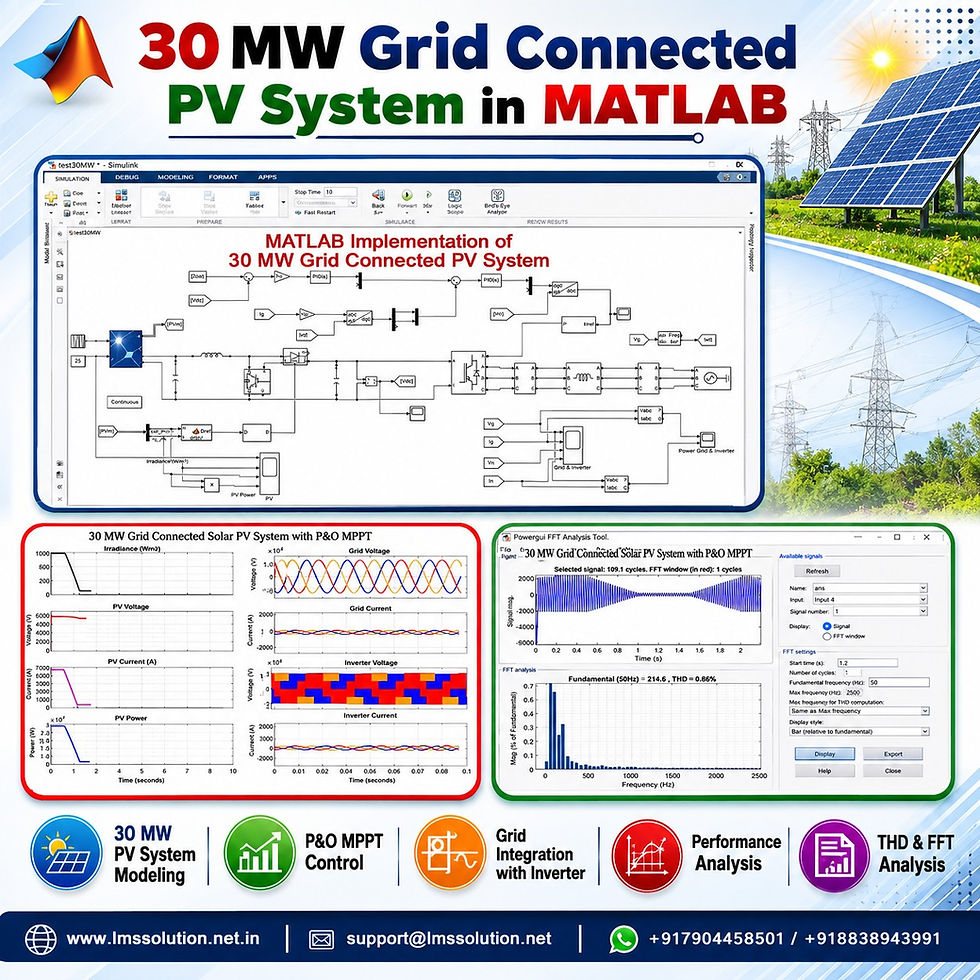
𝐒𝐲𝐬𝐭𝐞𝐦 𝐎𝐯𝐞𝐫𝐯𝐢𝐞𝐰
Parameter | Details |
System Type | Grid connected solar PV system |
Rated PV Power | 𝟑𝟎 𝐌𝐖 |
Software Platform | MATLAB Simulink |
MPPT Method | 𝐏&𝐎 MPPT |
DC-DC Converter | Boost converter |
Grid-Side Converter | Three-phase inverter |
Grid Voltage | 𝟏𝟏 𝐤𝐕 |
Grid Frequency | 𝟓𝟎 𝐇𝐳 |
DC-Link Voltage | Around 𝟐𝟎 𝐤𝐕 |
Power Transfer | PV power injected into grid as real power |
𝐌𝐚𝐢𝐧 𝐒𝐲𝐬𝐭𝐞𝐦 𝐏𝐚𝐫𝐭𝐬
Section | Function |
𝐏𝐕 𝐀𝐫𝐫𝐚𝐲 | Generates DC power from solar irradiation |
𝐁𝐨𝐨𝐬𝐭 𝐂𝐨𝐧𝐯𝐞𝐫𝐭𝐞𝐫 | Increases PV voltage and supports MPPT operation |
𝐏&𝐎 𝐌𝐏𝐏𝐓 | Tracks maximum power from the PV array |
𝐃𝐂 𝐋𝐢𝐧𝐤 | Maintains stable DC voltage for inverter operation |
𝐓𝐡𝐫𝐞𝐞-𝐏𝐡𝐚𝐬𝐞 𝐈𝐧𝐯𝐞𝐫𝐭𝐞𝐫 | Converts DC power into AC power |
𝐅𝐢𝐥𝐭𝐞𝐫 𝐈𝐧𝐝𝐮𝐜𝐭𝐨𝐫 | Improves grid current waveform quality |
𝐆𝐫𝐢𝐝 | Receives generated solar power |
𝐖𝐨𝐫𝐤𝐢𝐧𝐠 𝐏𝐫𝐨𝐜𝐞𝐬𝐬
The 𝟑𝟎 𝐌𝐖 𝐏𝐕 𝐚𝐫𝐫𝐚𝐲 receives solar irradiation and produces DC voltage and current.
The PV voltage and current are measured and given to the 𝐏&𝐎 𝐌𝐏𝐏𝐓 algorithm.
The MPPT controller calculates the proper duty cycle for the boost converter.
The boost converter adjusts the PV operating voltage to extract maximum power.
The boosted DC power is supplied to the 𝐃𝐂 𝐥𝐢𝐧𝐤.
The inverter converts DC power into three-phase AC power.
Voltage and current controllers regulate the inverter operation.
The generated AC power is injected into the 𝟏𝟏 𝐤𝐕 grid through the filter inductor.
Grid voltage, grid current, inverter voltage, inverter current, PV power, and DC-link voltage are monitored.
FFT analysis is performed to check current quality and THD performance.
𝐂𝐨𝐧𝐭𝐫𝐨𝐥 𝐒𝐭𝐫𝐚𝐭𝐞𝐠𝐲
𝐏&𝐎 𝐌𝐏𝐏𝐓 𝐂𝐨𝐧𝐭𝐫𝐨𝐥The P&O MPPT algorithm is used to operate the PV array near its maximum power point. It continuously checks the change in PV voltage and power, then adjusts the boost converter duty cycle.
𝐁𝐨𝐨𝐬𝐭 𝐂𝐨𝐧𝐯𝐞𝐫𝐭𝐞𝐫 𝐂𝐨𝐧𝐭𝐫𝐨𝐥The boost converter increases the PV output voltage and helps the PV array operate at the required maximum power point.
𝐃𝐂-𝐋𝐢𝐧𝐤 𝐕𝐨𝐥𝐭𝐚𝐠𝐞 𝐂𝐨𝐧𝐭𝐫𝐨𝐥The DC-link voltage is maintained around 𝟐𝟎 𝐤𝐕 to support stable inverter operation and grid power transfer.
𝐈𝐧𝐯𝐞𝐫𝐭𝐞𝐫 𝐂𝐮𝐫𝐫𝐞𝐧𝐭 𝐂𝐨𝐧𝐭𝐫𝐨𝐥The inverter control uses voltage and current regulation. The direct-axis current is used for real power transfer, while the reactive power reference is kept zero.
𝐒𝐢𝐦𝐮𝐥𝐚𝐭𝐢𝐨𝐧 𝐑𝐞𝐬𝐮𝐥𝐭𝐬
Result Parameter | Observed Value |
Initial Irradiation | 𝟏𝟎𝟎𝟎 W/m² |
Low Irradiation | 𝟏𝟎𝟎 W/m² |
PV Voltage at High Irradiation | Around 𝟓𝟎𝟎𝟎 V |
PV Current at High Irradiation | Around 𝟔𝟎𝟎𝟎 A |
PV Power at High Irradiation | Around 𝟑𝟎 𝐌𝐖 |
DC-Link Voltage | Around 𝟐𝟎 𝐤𝐕 |
Grid Voltage | 𝟏𝟏 𝐤𝐕 |
Grid Frequency | 𝟓𝟎 𝐇𝐳 |
𝐈𝐫𝐫𝐚𝐝𝐢𝐚𝐭𝐢𝐨𝐧 𝐕𝐚𝐫𝐢𝐚𝐭𝐢𝐨𝐧 𝐑𝐞𝐬𝐩𝐨𝐧𝐬𝐞
Time Period | Irradiation Condition | System Response |
0 to 0.5 s | 𝟏𝟎𝟎𝟎 W/m² | PV power reaches around 𝟑𝟎 𝐌𝐖 |
After 0.5 s | Reduced to 𝟏𝟎𝟎 W/m² | PV current and PV power decrease |
Around 1.5 s | Increased again to 𝟏𝟎𝟎𝟎 W/m² | PV voltage, current, and power increase |
High irradiation condition | 𝟏𝟎𝟎𝟎 W/m² | Grid and inverter power increase |
Low irradiation condition | 𝟏𝟎𝟎 W/m² | Current magnitude reduces, waveform remains sinusoidal |
𝐓𝐇𝐃 𝐚𝐧𝐝 𝐅𝐅𝐓 𝐀𝐧𝐚𝐥𝐲𝐬𝐢𝐬
Checking Time | THD Value |
0.5 s | Around 𝟎.𝟖𝟏% |
1.2 s | Around 𝟎.𝟖𝟔% |
1.8 s | Around 𝟎.𝟒𝟕% |
Current Quality Requirement | Less than 𝟓% |
Result | THD maintained within acceptable limit |
The FFT result shows that the grid current quality is good, and the THD remains below 𝟏%. This confirms that the inverter and filter arrangement provide clean current injection into the grid.
𝐊𝐞𝐲 𝐅𝐞𝐚𝐭𝐮𝐫𝐞𝐬
• Complete 𝟑𝟎 𝐌𝐖 grid connected PV system in MATLAB Simulink• P&O MPPT based maximum power extraction• Boost converter design for PV voltage control• Three-phase inverter connected to 𝟏𝟏 𝐤𝐕 grid• DC-link voltage maintained around 𝟐𝟎 𝐤𝐕• Real power injection from PV system to grid• Grid voltage and grid current measurement included• Inverter voltage and inverter current analysis included• FFT and THD analysis for current quality checking• Suitable for renewable energy and power electronics learning
𝐀𝐩𝐥𝐢𝐜𝐚𝐭𝐢𝐨𝐧𝐬
• Large-scale solar PV system analysis• Grid connected renewable energy simulation• MPPT controller study using MATLAB Simulink• Boost converter and inverter control learning• Power quality and THD analysis• PV power injection into utility grid• Renewable energy research and training• Power electronics control system study
𝐖𝐡𝐲 𝐓𝐡𝐢𝐬 𝐌𝐨𝐝𝐞𝐥 𝐢𝐬 𝐔𝐬𝐞𝐟𝐮𝐥
User Type | Benefit |
Students | Easy understanding of PV, MPPT, inverter, and grid connection |
Researchers | Helpful for studying PV power control and grid integration |
Engineers | Useful for analyzing practical grid connected PV behavior |
Trainers | Suitable for explaining renewable energy simulation concepts |
MATLAB Users | Clear Simulink-based implementation for learning and analysis |
𝐂𝐨𝐧𝐜𝐥𝐮𝐬𝐢𝐨𝐧
The 𝟑𝟎 𝐌𝐖 𝐆𝐫𝐢𝐝 𝐂𝐨𝐧𝐧𝐞𝐜𝐭𝐞𝐝 𝐏𝐕 𝐒𝐲𝐬𝐭𝐞𝐦 𝐢𝐧 𝐌𝐀𝐓𝐋𝐀𝐁 provides a clear simulation platform for understanding large-scale solar PV generation, MPPT control, DC-DC boost conversion, inverter control, and grid power injection.
The model shows stable operation under irradiation changes, maintains the DC-link voltage around 𝟐𝟎 𝐤𝐕, delivers solar power to the 𝟏𝟏 𝐤𝐕 grid, and keeps current THD below 𝟏%. This makes it a valuable learning and research resource for solar PV and grid connected power system studies.


Comments