


3 MW Grid Connected PV System

3 MW Grid Connected PV System
𝐈𝐧𝐭𝐫𝐨𝐝𝐮𝐜𝐭𝐢𝐨𝐧
A 3 MW grid-connected solar PV system is a large-scale photovoltaic power conversion system designed to extract maximum available solar energy and transfer it efficiently to the utility grid.
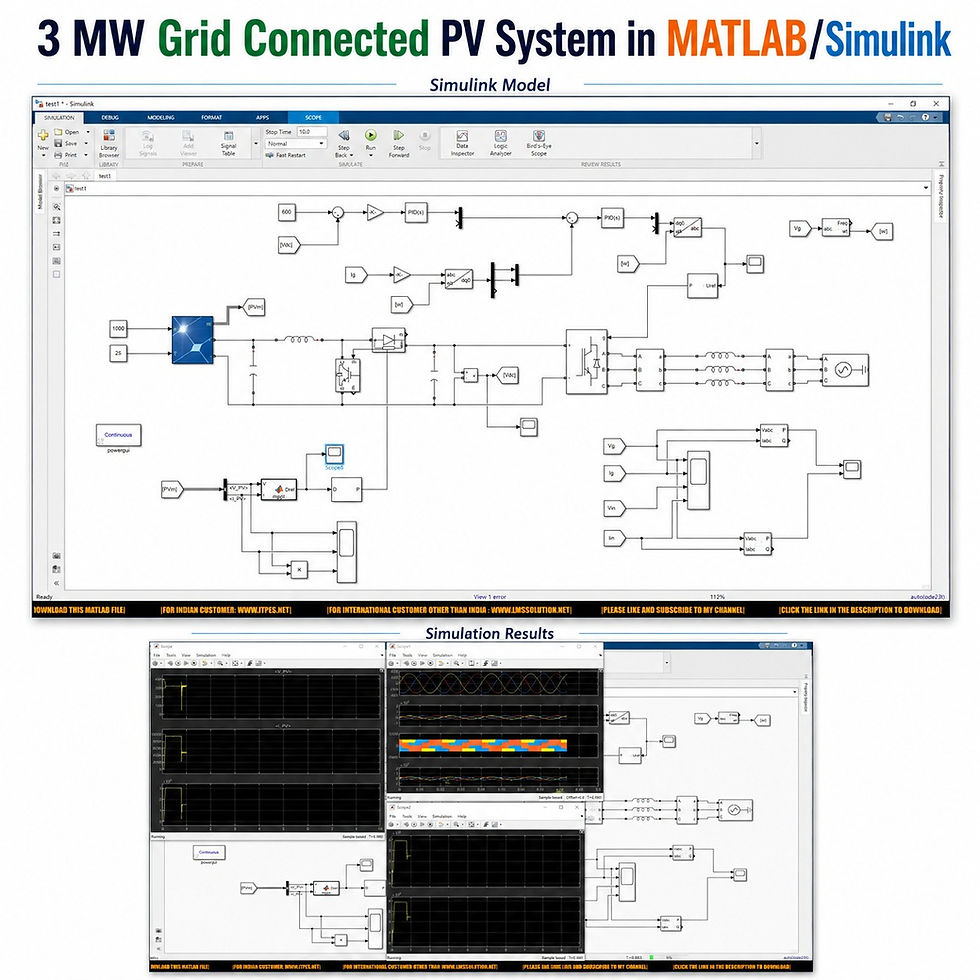
This MATLAB/Simulink model demonstrates the complete implementation of a 3 MW solar PV array, P&O MPPT-controlled boost converter, 600 V DC link, and three-phase grid-connected inverter.
The simulation is useful for:
Students learning solar PV and power electronics
Researchers studying grid-connected renewable energy systems
Engineers working with PV converters and inverter control
Understanding MPPT, DC-link regulation, PLL synchronization, and dq control
Analyzing PV operation under changing solar irradiation
𝐒𝐲𝐬𝐭𝐞𝐦 𝐎𝐯𝐞𝐫𝐯𝐢𝐞𝐰
The complete system uses a two-stage power conversion structure.
Stage 1 – DC–DC Conversion
Solar PV Array → Boost Converter → DC Link
Stage 2 – DC–AC Conversion
DC Link → Three-Phase Inverter → Inductive Filter → Grid
The system also includes:
P&O MPPT controller
PWM generation
DC-link voltage controller
Grid current controller
Phase-Locked Loop (PLL)
abc-to-dq transformation
dq-to-abc transformation
Grid voltage and current measurement
Inverter voltage and current measurement
Active and reactive power measurement
𝐌𝐚𝐢𝐧 𝐒𝐲𝐬𝐭𝐞𝐦 𝐏𝐚𝐫𝐚𝐦𝐞𝐭𝐞𝐫𝐬
Parameter | Value |
PV system rated power | Approximately 3 MW |
Individual PV module rating | 213.15 W |
PV panels connected in series | 11 |
Parallel strings | 1300 |
PV maximum power | Approximately 3.04 MW |
PV voltage at maximum power | Approximately 319 V |
PV current | Approximately 9500 A |
Standard irradiation | 1000 W/m² |
Temperature | 25 °C |
DC-link reference voltage | 600 V |
Boost converter switching frequency | 10 kHz |
Grid voltage | 400 V |
Grid frequency | 50 Hz |
Reduced irradiation condition | 500 W/m² |
PV/grid power at reduced irradiation | Approximately 1.5 MW |
𝐒𝐨𝐥𝐚𝐫 𝐏𝐕 𝐀𝐫𝐫𝐚𝐲
The first part of the MATLAB/Simulink model is the large-scale solar PV array.
The PV array is configured using:
213.15 W solar PV modules
11 modules in series
1300 parallel strings
Approximately 319 V at the maximum power operating region
Approximately 3.04 MW maximum PV power
Approximately 9500 A PV current
Two constant inputs are provided to the PV array:
PV Input | Initial Value |
Solar irradiation | 1000 W/m² |
Temperature | 25 °C |
These inputs allow the behavior of the PV system to be studied under different environmental conditions.
𝐅𝐢𝐫𝐬𝐭 𝐒𝐭𝐚𝐠𝐞: 𝐁𝐨𝐨𝐬𝐭 𝐂𝐨𝐧𝐯𝐞𝐫𝐭𝐞𝐫
The DC output generated by the PV array is connected to a boost converter.
The boost converter contains:
Input inductor
IGBT switching device
Diode
Output capacitor
Voltage measurement
PWM control
MPPT controller
The primary purpose of this converter is to operate the PV array at its optimum operating point while supplying power to the common DC link.
Main functions of the boost converter
Receives variable DC power from the PV array
Controls the PV operating point
Performs DC voltage boosting
Transfers extracted PV power to the DC link
Responds to changes in solar irradiation
𝐏&𝐎 𝐌𝐏𝐏𝐓 𝐂𝐨𝐧𝐭𝐫𝐨𝐥
A Perturb and Observe (P&O) Maximum Power Point Tracking algorithm is used to obtain maximum available power from the PV array.
The MPPT controller receives:
PV voltage
PV current
The controller generates:
Boost converter duty cycle
The P&O logic is implemented using a MATLAB Function block.
MPPT control flow
PV Voltage + PV Current↓P&O MPPT Algorithm↓Duty Cycle↓PWM Generation↓IGBT Switching↓Maximum PV Power Extraction
The converter switching frequency is maintained at 10 kHz.
𝐏𝐕 𝐌𝐞𝐚𝐬𝐮𝐫𝐞𝐦𝐞𝐧𝐭
The simulation continuously monitors important photovoltaic quantities.
Measured Quantity | Purpose |
PV voltage | Monitor solar array operating voltage |
PV current | Monitor generated current |
PV power | Evaluate extracted solar power |
DC-link voltage | Verify DC bus regulation |
PV voltage and current are also processed to determine the instantaneous PV output power.
𝐒𝐞𝐜𝐨𝐧𝐝 𝐒𝐭𝐚𝐠𝐞: 𝐆𝐫𝐢𝐝-𝐂𝐨𝐧𝐧𝐞𝐜𝐭𝐞𝐝 𝐈𝐧𝐯𝐞𝐫𝐭𝐞𝐫
After completion of the DC–DC stage, the PV power is transferred to the grid through a three-phase voltage source inverter.
A Universal Bridge using IGBT/diode switching devices is used for DC-to-AC conversion.
The inverter section consists of:
Universal Bridge
IGBT/diode switches
Three-phase voltage and current measurement
Inductive filter
Grid connection
PWM controller
The inverter is connected to a:
400 V
50 Hz
Three-phase grid
𝐃𝐂-𝐋𝐢𝐧𝐤 𝐕𝐨𝐥𝐭𝐚𝐠𝐞 𝐂𝐨𝐧𝐭𝐫𝐨𝐥
The DC-link voltage is regulated at:
600 V
The measured DC-link voltage is compared with its reference value.
The voltage error is processed using a PI controller.
The PI controller produces the required direct-axis current reference, which controls the active power transferred between the inverter and the grid.
DC-link control sequence
DC-Link Reference↓Compare with Measured DC Voltage↓PI Controller↓Direct-Axis Current Reference↓Current Controller↓Inverter Control
Maintaining a stable DC-link voltage is essential for reliable inverter operation and controlled grid power injection.
𝐏𝐋𝐋 𝐚𝐧𝐝 𝐆𝐫𝐢𝐝 𝐒𝐲𝐧𝐜𝐡𝐫𝐨𝐧𝐢𝐳𝐚𝐭𝐢𝐨𝐧
A Phase-Locked Loop (PLL) is used to synchronize the inverter control with the utility grid.
The PLL obtains synchronization information from the grid voltage and provides the angular information required for coordinate transformations.
Its main purposes include:
Tracking the grid phase
Synchronizing inverter output with the grid
Supporting abc-to-dq transformation
Supporting dq-to-abc transformation
Maintaining proper grid-connected operation
𝐝𝐪 𝐂𝐮𝐫𝐫𝐞𝐧𝐭 𝐂𝐨𝐧𝐭𝐫𝐨𝐥
The measured three-phase grid currents are transformed from the abc reference frame to the dq reference frame.
The control system then regulates the direct- and quadrature-axis current components.
Current control process
Grid Current↓abc-to-dq Transformation↓Compare with Current References↓PI Current Controllers↓dq Voltage Commands↓dq-to-abc Transformation↓PWM Generator↓Three-Phase Inverter
This control approach provides effective regulation of the inverter current before power is injected into the grid.
𝐏𝐖𝐌 𝐈𝐧𝐯𝐞𝐫𝐭𝐞𝐫 𝐂𝐨𝐧𝐭𝐫𝐨𝐥
After current regulation, the generated voltage commands are converted from dq quantities back into three-phase abc signals.
These signals are supplied to the PWM generator.
The PWM generator produces switching pulses for the Universal Bridge, controlling the IGBT switches and therefore the inverter output voltage and current.
𝐈𝐧𝐝𝐮𝐜𝐭𝐢𝐯𝐞 𝐆𝐫𝐢𝐝 𝐅𝐢𝐥𝐭𝐞𝐫
An inductive filter is installed between the inverter and the utility grid.
Its main functions are to:
Improve inverter output current quality
Reduce switching-related current components
Provide smoother grid current
Support controlled grid power injection
Interface the inverter with the three-phase grid
𝐏𝐨𝐰𝐞𝐫 𝐌𝐞𝐚𝐬𝐮𝐫𝐞𝐦𝐞𝐧𝐭
Several electrical quantities are measured at the grid and inverter sides.
Monitored signals
Grid voltage
Grid current
Inverter voltage
Inverter current
Grid-side active power
Grid-side reactive power
Inverter-side active power
Inverter-side reactive power
Positive-sequence measurements are used for evaluating power on the grid and inverter sides.
𝐖𝐨𝐫𝐤𝐢𝐧𝐠 𝐏𝐫𝐨𝐜𝐞𝐬𝐬
The complete operation can be summarized as follows:
Solar irradiation falls on the PV array.
The PV array generates DC voltage and current.
The P&O MPPT algorithm monitors PV voltage and current.
MPPT generates the required boost converter duty cycle.
PWM pulses operate the boost converter IGBT at 10 kHz.
Maximum available PV power is transferred to the DC link.
The DC-link controller regulates the bus voltage at 600 V.
The PLL synchronizes the inverter controller with the grid.
Grid currents are converted from abc to dq quantities.
PI controllers regulate the required dq currents.
dq control signals are transformed back into three-phase quantities.
PWM pulses operate the three-phase inverter.
The inductive filter conditions the inverter output.
Solar PV power is transferred to the 400 V, 50 Hz grid.
𝐂𝐨𝐧𝐭𝐫𝐨𝐥 𝐒𝐭𝐫𝐚𝐭𝐞𝐠𝐲
Control Section | Technique | Main Function |
PV power extraction | P&O MPPT | Extract maximum available PV power |
Boost converter | PWM duty-cycle control | Control DC–DC conversion |
DC-link voltage | PI controller | Maintain 600 V DC link |
Grid synchronization | PLL | Synchronize with 50 Hz grid |
Grid current | dq-based PI control | Regulate inverter current |
Coordinate conversion | abc ↔ dq | Simplify three-phase control |
Inverter switching | PWM | Generate IGBT gate pulses |
𝐒𝐢𝐦𝐮𝐥𝐚𝐭𝐢𝐨𝐧 𝐑𝐞𝐬𝐮𝐥𝐭𝐬
The simulation demonstrates successful operation of the grid-connected PV system.
At 1000 W/m² irradiation
PV power reaches approximately 3 MW
DC-link voltage remains regulated at 600 V
The inverter operates in synchronization with the grid
Generated PV power is transferred to the utility grid
At 500 W/m² irradiation
When solar irradiation is reduced from 1000 W/m² to 500 W/m²:
PV generation decreases
Grid-side power also decreases
PV/grid power becomes approximately 1.5 MW
The MPPT controller continues tracking the available maximum power
Irradiation comparison
Operating Condition | Irradiation | Approximate Power |
High irradiation | 1000 W/m² | 3 MW |
Reduced irradiation | 500 W/m² | 1.5 MW |
This response demonstrates the ability of the P&O MPPT controller to adjust the operating point when solar irradiation changes.
𝐊𝐞𝐲 𝐅𝐞𝐚𝐭𝐮𝐫𝐞𝐬
3 MW grid-connected solar PV system
Large-scale PV array configuration
Approximately 3.04 MW maximum PV capacity
P&O MPPT implementation
MATLAB Function-based MPPT logic
10 kHz boost converter switching
Two-stage power conversion
IGBT-based DC–DC boost converter
Three-phase IGBT inverter
600 V regulated DC link
400 V, 50 Hz grid
PLL-based grid synchronization
abc-to-dq current transformation
PI-based voltage and current regulation
dq-to-abc conversion
PWM inverter switching
Grid-side and inverter-side power measurement
Performance analysis under changing solar irradiation
𝐀𝐩𝐩𝐥𝐢𝐜𝐚𝐭𝐢𝐨𝐧𝐬
This MATLAB/Simulink model is useful for studying:
Large-scale solar PV generation
Grid-connected photovoltaic systems
Renewable energy integration
Solar inverter control
MPPT techniques
DC-link voltage regulation
Grid synchronization
dq current control
Power electronic converter operation
Grid power transfer
PV performance under variable irradiation
Active and reactive power analysis
𝐖𝐡𝐲 𝐓𝐡𝐢𝐬 𝐌𝐨𝐝𝐞𝐥 𝐢𝐬 𝐔𝐬𝐞𝐟𝐮𝐥
The model combines the major control concepts required for a practical grid-connected PV system within a single simulation environment.
Students and researchers can understand:
How a multi-megawatt PV array is configured
How P&O MPPT controls a boost converter
How DC voltage is stabilized before inversion
How a three-phase inverter is synchronized with the utility grid
How dq-based current control operates
How PV generation changes with irradiation
How solar power is delivered from the DC side to the AC grid
𝐂𝐨𝐧𝐜𝐥𝐮𝐬𝐢𝐨𝐧
The 3 MW Grid Connected PV System in MATLAB/Simulink demonstrates a complete two-stage solar power conversion system from PV generation to grid power injection.
The solar array produces approximately 3 MW at 1000 W/m², while the P&O MPPT controller regulates the boost converter for maximum power extraction. The DC-link voltage is maintained at 600 V, and a PLL-synchronized three-phase inverter transfers the generated power to a 400 V, 50 Hz grid.
When irradiation is reduced to 500 W/m², the output power decreases to approximately 1.5 MW, showing the response of the PV and MPPT system to changing environmental conditions.
Overall, the simulation provides a clear platform for understanding large-scale solar PV modeling, MPPT control, DC–DC conversion, inverter control, grid synchronization, and grid-connected power transfer.


Comments