


MATLAB Simulation of Off Grid Solar PV Battery System

MATLAB Simulation of Off Grid Solar PV Battery System
𝐈𝐧𝐭𝐫𝐨𝐝𝐮𝐜𝐭𝐢𝐨𝐧
The MATLAB simulation of an off-grid solar PV battery system demonstrates how solar energy, battery storage, an inverter, and a backup AC source can work together to supply a residential AC load.
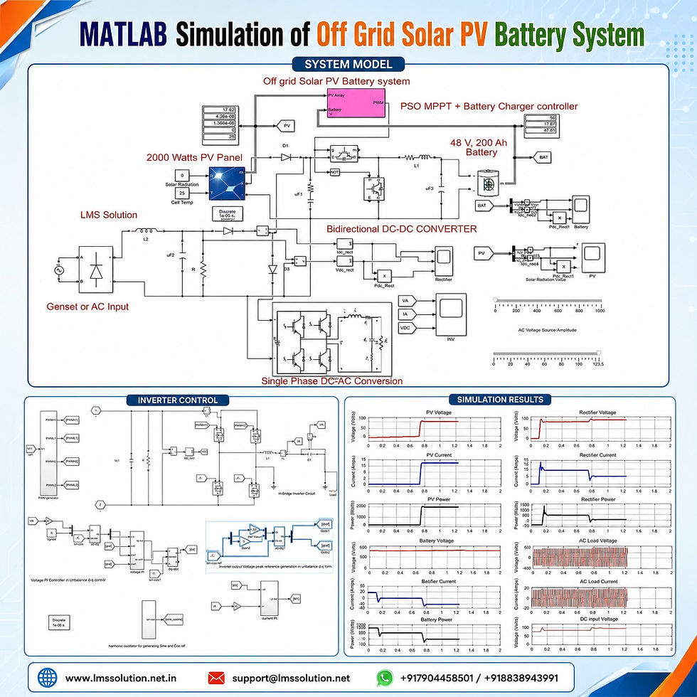
The model uses a PSO-based MPPT controller to extract maximum power from the solar PV array. A battery charger controller supervises the charging process, while a bidirectional DC–DC converter manages power flow between the DC bus and the battery.
The system is designed to maintain continuous load supply under changing solar irradiation, low battery conditions, and backup-generator operation.
𝐒𝐲𝐬𝐭𝐞𝐦 𝐎𝐯𝐞𝐫𝐯𝐢𝐞𝐰
The off-grid solar PV battery system contains the following main sections:
A 2 kW solar PV array as the primary energy source
A PSO MPPT controller for maximum power extraction
A 48 V, 200 Ah battery for energy storage
A bidirectional DC–DC converter for battery charging and discharging
A single-phase inverter for supplying the AC load
Voltage and current controllers for inverter regulation
A rectifier-supported generator or AC backup input
Measurement blocks for PV, battery, rectifier, inverter, and load variables
Main System Parameters
Parameter | Value |
Total PV array rating | 2000 W |
Individual PV module rating | 250 W |
Modules connected in series | 4 |
Parallel strings | 2 |
Voltage at maximum power point | 30.9 V per module |
Current at maximum power point | 8.1 A per module |
Battery nominal voltage | 48 V |
Battery rated capacity | 200 Ah |
Maximum tested solar irradiation | 1000 W/m² |
Power converter type | Bidirectional DC–DC converter |
AC conversion stage | Single-phase inverter |
MPPT method | Particle Swarm Optimization |
𝐌𝐚𝐢𝐧 𝐒𝐲𝐬𝐭𝐞𝐦 𝐂𝐨𝐦𝐩𝐨𝐧𝐞𝐧𝐭𝐬
1. Solar PV Array
The solar PV array acts as the main power source. Its output depends mainly on solar irradiation and cell temperature.
Higher irradiation produces greater PV current and power.
Lower irradiation reduces the available peak power.
Zero irradiation results in almost zero PV generation.
The PV array supplies the AC load through the inverter.
Excess solar energy is transferred to the battery.
2. PSO MPPT Controller
The Particle Swarm Optimization MPPT controller receives the following inputs:
PV voltage
PV current
The controller calculates a suitable duty cycle for the power converter. This duty cycle allows the PV array to operate close to its maximum power point under varying environmental conditions.
3. Battery Energy Storage
The model uses a 48 V, 200 Ah battery to store surplus solar energy and support the load when PV generation is insufficient.
The battery operates in three basic conditions:
Charging mode: Excess PV or generator power charges the battery.
Discharging mode: The battery supplies the AC load during low PV generation.
Idle mode: The battery power remains near zero when charging or discharging is unnecessary.
4. Bidirectional DC–DC Converter
The bidirectional converter controls power transfer in both directions:
DC bus to battery during charging
Battery to DC bus during discharging
This converter enables coordinated energy management between the PV source, battery, backup supply, and AC load.
5. Single-Phase Inverter
The inverter converts DC power into regulated single-phase AC power.
Its control system includes:
Output-voltage measurement
Output-current measurement
Reference-voltage generation
Voltage PI controller
Current PI controller
PWM pulse generation
H-bridge switching circuit
Output filtering
6. Generator or AC Backup Input
A generator set or external AC source can be connected when:
Solar PV power is unavailable
Battery state of charge is low
The battery cannot support the complete AC load
Additional charging power is required
The AC input is converted into DC through a rectifier and filter before being supplied to the DC bus.
𝐖𝐨𝐫𝐤𝐢𝐧𝐠 𝐏𝐫𝐨𝐜𝐞𝐬𝐬
The system gives first preference to available solar PV power.
Solar Power Available
When sufficient solar energy is available:
The PV array generates DC power.
The PSO MPPT controller extracts the maximum available power.
The inverter uses PV power to supply the AC load.
Excess PV power is sent to the battery.
The battery operates in charging mode.
The generator or AC backup source remains disconnected.
Solar Power Lower Than Load Demand
When PV generation decreases:
Available PV power is supplied to the AC load.
The battery supplies the remaining load demand.
The bidirectional converter operates in discharging mode.
The inverter continues to maintain the required AC voltage.
The load receives uninterrupted power.
Solar Power Unavailable
When solar irradiation becomes zero:
PV voltage, current, and power decrease to nearly zero.
The battery becomes the primary DC source.
Battery current changes according to the adopted sign convention.
The battery supplies power through the DC bus.
The inverter converts battery power into AC power.
The AC load continues operating without grid support.
Low Battery State of Charge
When PV power is unavailable and battery charge is low:
The generator or AC input is connected.
The AC supply passes through the rectifier.
Rectified DC power supports the inverter.
The AC load receives power from the backup source.
Additional available power can charge the battery.
Battery discharge is reduced or stopped.
𝐎𝐩𝐞𝐫𝐚𝐭𝐢𝐧𝐠 𝐌𝐨𝐝𝐞𝐬
Operating Mode | PV Condition | Battery Condition | Backup Input | Load Supply |
Solar charging mode | High PV power | Charging | Off | Mainly PV |
PV and battery mode | Moderate PV power | Discharging partially | Off | PV and battery |
Battery-only mode | PV power unavailable | Discharging | Off | Battery |
Backup mode | No PV and low battery SOC | Protected or charging | On | Generator or AC input |
Combined PV and backup mode | Partial PV power | Charging or idle | On | PV and backup source |
Battery idle mode | Balanced source and load power | Near-zero power flow | As required | Available source |
𝐂𝐨𝐧𝐭𝐫𝐨𝐥 𝐒𝐭𝐫𝐚𝐭𝐞𝐠𝐲
PSO MPPT and Battery Charger Control
The MPPT and battery charging functions operate together.
The controller performs the following tasks:
Measures PV voltage and PV current
Searches for the maximum PV power operating point
Generates the converter duty cycle
Monitors battery state of charge
Measures battery terminal voltage
Detects battery overvoltage conditions
Enables or blocks converter switching
Prevents unnecessary battery charging
The MPPT-generated duty cycle is allowed only when the battery charging conditions are satisfied. Converter operation is blocked when the battery reaches its charging limit or exceeds the permitted voltage level.
Inverter Voltage Control
The measured inverter voltage is processed through a reference-frame control structure.
The voltage-control stage:
Measures the inverter output voltage
Generates the required voltage references
Compares actual and reference voltage components
Processes the errors through PI controllers
Produces the reference current signal
Inverter Current Control
The current-control stage:
Measures the inverter output current
Compares measured current with reference current
Processes the current error using a PI controller
Generates the inverter modulating signal
Sends the modulating signal to the PWM generator
Controls the H-bridge inverter switches
This cascaded control structure helps maintain a stable sinusoidal AC voltage across the load.
𝐒𝐢𝐦𝐮𝐥𝐚𝐭𝐢𝐨𝐧 𝐑𝐞𝐬𝐮𝐥𝐭𝐬
Case 1: Solar Irradiation at 1000 W/m²
Under high solar irradiation, the PV array generates significant power.
Observed Variable | Approximate Value or Condition |
Solar irradiation | 1000 W/m² |
PV voltage | Around 100 V |
PV current | Around 16 A |
PV power | Around 1700 W |
Battery operation | Charging |
Backup generator power | Zero |
AC load supply | Supplied by PV |
Excess PV power | Used for battery charging |
The negative battery current shown in the model represents charging according to the selected measurement convention.
Case 2: Solar Irradiation Reduced to Zero
When solar irradiation becomes zero, PV generation stops.
Observed Variable | Condition |
PV voltage | Decreases significantly |
PV current | Nearly zero |
PV power | Nearly zero |
Battery operation | Discharging |
Backup source | Initially disconnected |
AC load supply | Supplied by battery |
Inverter output | Maintained continuously |
The battery current changes from the charging direction to the discharging direction when the battery begins supplying the load.
Case 3: Backup Generator Connected
When the battery state of charge is low, the generator or AC input is connected.
Observed Variable | Condition |
Rectifier voltage | Increases after source connection |
Rectifier current | Increases |
Rectifier power | Supplies the DC bus |
AC load supply | Maintained by backup input |
Battery power | Reduced or maintained near a safe level |
PV power | Zero or insufficient |
System continuity | Maintained |
Case 4: PV Power Increased During Generator Operation
When solar irradiation increases while the generator is active:
PV voltage, current, and power increase.
PV power begins supporting the AC load.
Excess PV power can charge the battery.
Generator power sharing decreases.
Backup-source loading is reduced.
Generator contribution falls to approximately 500 W in the demonstrated condition.
Case 5: PV Power Reduced Again
When PV generation is reduced after the combined operating condition:
PV contribution decreases.
Battery power may enter an idle condition.
The generator supplies the required load power.
Rectifier power increases according to demand.
The AC load voltage remains regulated.
𝐏𝐨𝐰𝐞𝐫 𝐅𝐥𝐨𝐰 𝐏𝐫𝐢𝐨𝐫𝐢𝐭𝐲
The simulated energy-management priority can be summarized as follows:
Solar PV power supplies the AC load first.
Excess solar power charges the battery.
The battery supports the load when PV power is insufficient.
The battery supplies the complete load when PV power is unavailable.
The generator or AC input is activated when battery energy becomes low.
Available backup power supplies the load and can recharge the battery.
𝐊𝐞𝐲 𝐅𝐞𝐚𝐭𝐮𝐫𝐞𝐬
Complete off-grid solar PV battery system developed in MATLAB/Simulink
2 kW PV array with series-parallel module arrangement
PSO-based maximum power point tracking
Battery charging protection based on SOC and voltage
Bidirectional battery charging and discharging
Single-phase H-bridge inverter topology
Cascaded voltage and current control
PWM-based inverter switching
Generator or utility AC backup provision
Rectifier and filtering stage for backup input
Continuous AC load supply under varying solar conditions
Multiple operating modes for energy-management analysis
Measurement of PV, battery, rectifier, inverter, and load parameters
Clear visualization of voltage, current, and power responses
𝐀𝐩𝐩𝐥𝐢𝐜𝐚𝐭𝐢𝐨𝐧𝐬
This MATLAB simulation can support learning and analysis in areas such as:
Residential off-grid solar power systems
Rural electrification
Solar-powered home energy systems
Battery charger control
Renewable energy conversion
Standalone inverter systems
Backup generator coordination
PV and battery energy management
Bidirectional converter control
Microgrid operating-mode analysis
MPPT algorithm evaluation
Power-electronics controller development
𝐖𝐡𝐨 𝐂𝐚𝐧 𝐔𝐬𝐞 𝐓𝐡𝐢𝐬 𝐌𝐨𝐝𝐞𝐥?
The simulation is suitable for:
Students learning solar PV and battery systems
Researchers studying MPPT control
Engineers working with standalone power systems
MATLAB/Simulink learners
Renewable-energy system designers
Power-electronics professionals
Users studying inverter voltage and current control
𝐁𝐞𝐧𝐞𝐟𝐢𝐭𝐬 𝐨𝐟 𝐭𝐡𝐞 𝐒𝐢𝐦𝐮𝐥𝐚𝐭𝐢𝐨𝐧
Demonstrates coordinated operation of PV, battery, inverter, and backup source
Explains power sharing under different irradiation levels
Shows battery charging and discharging behaviour
Helps analyse PSO MPPT performance
Illustrates DC–DC and DC–AC conversion stages
Provides measurable voltage, current, and power outputs
Supports controller testing without physical hardware
Allows operating conditions to be changed easily
Improves understanding of off-grid energy management
𝐂𝐨𝐧𝐜𝐥𝐮𝐬𝐢𝐨𝐧
The MATLAB simulation of an off-grid solar PV battery system provides a complete platform for studying renewable power generation, battery storage, inverter control, and backup-source coordination.
The PSO MPPT controller extracts maximum available solar power, while the bidirectional converter manages battery charging and discharging. The single-phase inverter maintains AC power delivery under varying PV conditions. When solar power and battery energy are insufficient, the generator or AC input supports the load and battery.
This model offers a practical and easy-to-understand approach for analysing off-grid solar energy management, battery charger control, converter operation, and uninterrupted AC load supply.


Comments